B2336-HORN CONTROL CIRCUIT LOW - FCM
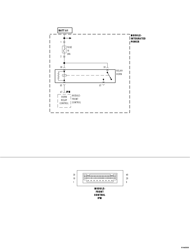
For a complete wiring diagram Refer to Section 8W.
- When Monitored:
Continuously.
- Set Condition:
If the Front Control Module (FCM) senses either excessively low or no voltage on the (X4) Horn Relay Control circuit.
| Possible Causes |
| (A43) FUSED B(+) CIRCUIT SHORTED TO GROUND |
| (X4) HORN RELAY CONTROL CIRCUIT SHORTED TO GROUND |
| (A1) / (A913) CIRCUIT OPEN TO HORN FUSE |
| (A43) FUSED B(+) CIRCUIT OPEN |
| (X4) HORN RELAY CONTROL CIRCUIT OPEN |
| HORN FUSE |
| HORN RELAY |
| INTEGRATED POWER MODULE (IPM) |
| FRONT CONTROL MODULE (FCM) |
Diagnostic Test
1.TEST FOR INTERMITTENT CONDITIONDoes the scan tool display: B2336 HORN CONTROL CIRCUIT LOW?
Yes
- Go To 2
No
- The conditions that caused this code to set are not present at this time. Using the wiring diagram/schematic as a guide, inspect the wiring and connectors.
- Perform BODY VERIFICATION TEST - VER 1. (Refer to 8 - ELECTRICAL/ELECTRONIC CONTROL MODULES - STANDARD PROCEDURE).
2.CHECK THE HORN FUSE
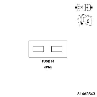
Is the Horn Fuse open?
Yes
- Go To 3
No
- Reinstall the Horn Fuse. Then, Go To 7.
3.CHECK FOR A SHORTED HORN RELAY
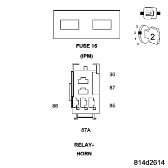
Does the scan tool display: B2336 HORN CONTROL CIRCUIT LOW?
Yes
- Go To 4
No
- Replace the original Horn Relay.
- Perform BODY VERIFICATION TEST - VER 1. (Refer to 8 - ELECTRICAL/ELECTRONIC CONTROL MODULES - STANDARD PROCEDURE).
4.CHECK THE (A43) FUSED B(+) CIRCUIT FOR A SHORT TO GROUND
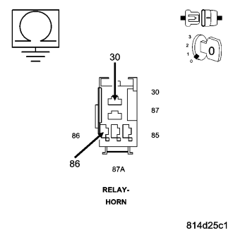
Is the resistance below 10k ohms?
Yes
- Replace the Integrated Power Module (IPM) in accordance with the Service Information.
- Perform BODY VERIFICATION TEST - VER 1. (Refer to 8 - ELECTRICAL/ELECTRONIC CONTROL MODULES - STANDARD PROCEDURE).
No
- Go To 5
5.CHECK THE (X4) HORN RELAY CONTROL CIRCUIT FOR A SHORT TO GROUND
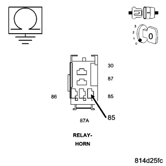
Is the resistance below 10k ohms?
Yes
- Replace the Integrated Power Module (IPM) in accordance with the Service Information.
- Perform BODY VERIFICATION TEST - VER 1. (Refer to 8 - ELECTRICAL/ELECTRONIC CONTROL MODULES - STANDARD PROCEDURE).
No
- Replace the Front Control Module (FCM) in accordance with the Service Information. Then, Go To 6.
6.CHECK FOR A SHORTED INTEGRATED POWER MODULE (IPM)
Does the scan tool display: B2336 HORN CONTROL CIRCUIT LOW?
Yes
- Replace the Integrated Power Module (IPM) in accordance with the Service Information.
- Perform BODY VERIFICATION TEST - VER 1. (Refer to 8 - ELECTRICAL/ELECTRONIC CONTROL MODULES - STANDARD PROCEDURE).
No
- Perform BODY VERIFICATION TEST - VER 1. (Refer to 8 - ELECTRICAL/ELECTRONIC CONTROL MODULES - STANDARD PROCEDURE).
7.CHECK FOR POWER TO THE HORN FUSE
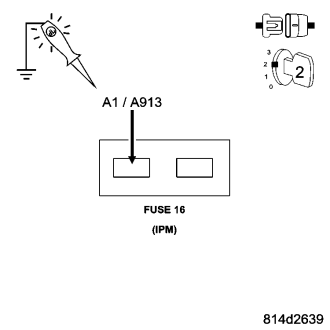
Does the test light illuminate brightly?
Yes
- Go To 8
No
- Repair the (A1) / (A913) circuit for an open.
- Perform BODY VERIFICATION TEST - VER 1. (Refer to 8 - ELECTRICAL/ELECTRONIC CONTROL MODULES - STANDARD PROCEDURE).
8.CHECK FOR AN OPEN HORN RELAY
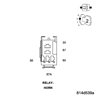
Does the scan tool display: B2336 HORN CONTROL CIRCUIT LOW?
Yes
- Go To 9
No
- Replace the original Horn Relay.
- Perform BODY VERIFICATION TEST - VER 1. (Refer to 8 - ELECTRICAL/ELECTRONIC CONTROL MODULES - STANDARD PROCEDURE).
9.CHECK THE (A43) FUSED B(+) CIRCUIT FOR AN OPEN
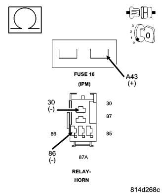
Is the resistance below 5.0 ohms?
Yes
- Go To 10
No
- Replace the Integrated Power Module (IPM) in accordance with the Service Information.
- Perform BODY VERIFICATION TEST - VER 1. (Refer to 8 - ELECTRICAL/ELECTRONIC CONTROL MODULES - STANDARD PROCEDURE).
10.CHECK THE (X4) HORN RELAY CONTROL CIRCUIT FOR AN OPEN
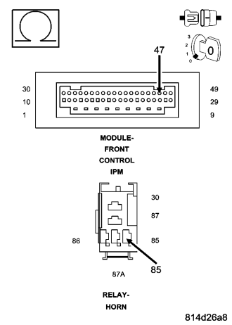
Is the resistance below 5.0 ohms?
Yes
- Replace the Front Control Module (FCM) in accordance with the Service Information.
- Perform BODY VERIFICATION TEST - VER 1. (Refer to 8 - ELECTRICAL/ELECTRONIC CONTROL MODULES - STANDARD PROCEDURE).
No
- Replace the Integrated Power Module (IPM) in accordance with the Service Information.
- Perform BODY VERIFICATION TEST - VER 1. (Refer to 8 - ELECTRICAL/ELECTRONIC CONTROL MODULES - STANDARD PROCEDURE).