P0562-BATTERY VOLTAGE LOW
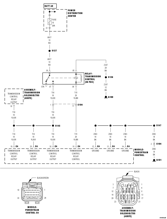
For a complete wiring diagram Refer to Section 8W.
Theory of Operation
Friction element distress could result from an insufficient supply voltage to properly control the solenoids. To prevent this possibility, the battery voltage is monitored and the system is placed in logical limp-in if the battery voltage drops below the limit.
- When Monitored:
With the engine running and the PCM has closed the Transmission Control Relay.
- Set Condition:
If the battery voltage of the Transmission Control Relay Output Sense circuit(s) to the PCM is less than 10.0 volts for the period of 15 seconds. Note: P0562 generally indicates a gradually falling battery voltage or a resistive connection(s) to the PCM. The DTC will also set if the battery voltage sensed at the PCM is less than 6.5-volts for 200ms or where Transmission Control Relay Output circuits are less than 7.2-volts for 200ms.
| Possible Causes |
| RELATED CHARGING SYSTEM DTCS |
| (Z908, Z977) GROUND CIRCUIT OPEN OR HIGH RESISTANCE |
| (A104) FUSED B(+) CIRCUIT TO PCM OPEN OR HIGH RESISTANCE |
| (T16) TRANSMISSION CONTROL RELAY OUTPUT CIRCUIT OPEN OR HIGH RESISTANCE |
| TRANSMISSION CONTROL RELAY |
| POWERTRAIN CONTROL MODULE |
Always perform the 45RFE/545RFE Pre-Diagnostic Troubleshooting procedure before proceeding. (Refer to 21 - TRANSMISSION/TRANSAXLE/AUTOMATIC - 45RFE/545RFE - STANDARD PROCEDURE)
Diagnostic Test
1.RELATED CHARGING SYSTEM DTCSAre there any related Charging System DTCs also present?
Yes
- Refer to the Charging System category and repair any Engine Charging System DTCs, before testing DTC P0562. NOTE: After repairing the Engine Charging System DTCs, perform the Transmission Verification test to verify the transmission was not damaged.
- Perform 45RFE/545RFE TRANSMISSION VERIFICATION TEST. (Refer to 21 - TRANSMISSION/TRANSAXLE/AUTOMATIC - 45RFE/545RFE - STANDARD PROCEDURE)
No
- Go To 2
2.CONDITION P0562 PRESENT
NOTE: Generator, battery, and charging system must be fully functional before performing this test.
NOTE: This counter only applies to the last DTC set.
Is the STARTS SINCE SET counter set at 0?
Yes
- Go To 3
No
- Go To 7
3.CHECK THE (Z908, Z977) GROUND CIRCUITS
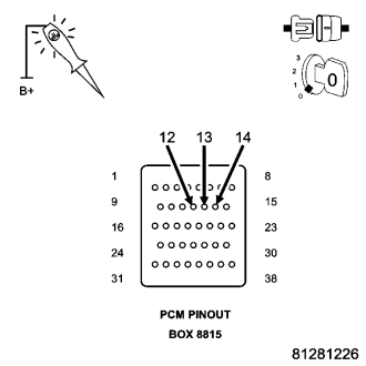
NOTE: Check connectors - Clean/repair as necessary.
CAUTION: Do not probe the PCM harness connectors. Probing the PCM harness connectors will damage the PCM terminals resulting in poor terminal to pin connection. Install Miller tool #8815 to perform diagnosis.
NOTE: The test light must illuminate brightly. Compare the brightness to that of a direct connection to the battery.
Does the test light illuminate brightly for the PCM (Z908, Z977) Ground circuits?
Yes
- Go To 4
No
- Repair the (Z908, Z977) Ground circuit(s) for an open or high resistance.
- Perform 45RFE/545RFE TRANSMISSION VERIFICATION TEST. (Refer to 21 - TRANSMISSION/TRANSAXLE/AUTOMATIC - 45RFE/545RFE - STANDARD PROCEDURE)
4.CHECK THE (A104) FUSED B(+) CIRCUIT
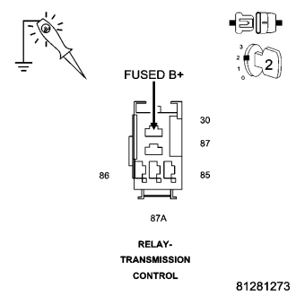
Does the test light illuminate brightly?
Yes
- Go To 5
No
- Repair the (A104) Fused B(+) circuit for an open or high resistance.
- Perform 45RFE/545RFE TRANSMISSION VERIFICATION TEST. (Refer to 21 - TRANSMISSION/TRANSAXLE/AUTOMATIC - 45RFE/545RFE - STANDARD PROCEDURE)
5.CHECK THE (T16) TRANSMISSION CONTROL RELAY OUTPUT CIRCUIT
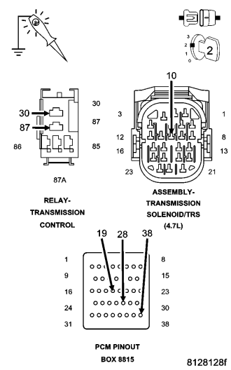
NOTE: Check connectors - Clean/repair as necessary.
Does the test light illuminate brightly?
Yes
- Go To 6
No
- Repair the (T16) Transmission Control Relay Output circuit for an open or high resistance.
- Perform 45RFE/545RFE TRANSMISSION VERIFICATION TEST. (Refer to 21 - TRANSMISSION/TRANSAXLE/AUTOMATIC - 45RFE/545RFE - STANDARD PROCEDURE)
6.CHECK THE TRANSMISSION CONTROL RELAY
Is the scan tool voltage within 1.0 volt of the battery voltage?
Yes
- Replace the Transmission Control Relay.
- Perform 45RFE/545RFE TRANSMISSION VERIFICATION TEST. (Refer to 21 - TRANSMISSION/TRANSAXLE/AUTOMATIC - 45RFE/545RFE - STANDARD PROCEDURE)
No
- Using the schematics as a guide, check the Powertrain Control Module (PCM) terminals for corrosion, damage, or terminal push out. Pay particular attention to all power and ground circuits. If no problems are found, replace the PCM per the Service Information. With the scan tool, perform QUICK LEARN.
- Perform 45RFE/545RFE TRANSMISSION VERIFICATION TEST. (Refer to 21 - TRANSMISSION/TRANSAXLE/AUTOMATIC - 45RFE/545RFE - STANDARD PROCEDURE)
7.CHECK WIRING AND CONNECTORS
Where there any problems found?
Yes
- Repair as necessary.
- Perform 45RFE/545RFE TRANSMISSION VERIFICATION TEST. (Refer to 21 - TRANSMISSION/TRANSAXLE/AUTOMATIC - 45RFE/545RFE - STANDARD PROCEDURE)
No
- Test Complete.