P2074-MAP/TPS CORRELLATION - HIGH AIRFLOW/VACUUM LEAK DETECTED

For a complete wiring diagram Refer to Section 8W.
Theory of Operation
This DTC sets when an unexpected high intake manifold air flow condition exists that can lead to increased engine speed and puts the NGC into a High Air flow Protection limiting mode. The High Air flow Protection feature includes RPM limits for when a Throttle and/or MAP sensor limp-in fault is present.
- When Monitored:
During all drive modes
- Set Condition:
If vacuum drops below 1.5"Hg with engine RPM greater than 2000 RPM and closed throttle. One Trip Fault. Three good trips to turn off the MIL.
| Possible Causes |
| VACUUM LEAK |
| RESISTANCE IN THE (F856) 5-VOLT SUPPLY CIRCUIT |
| (F856) 5-VOLT SUPPLY CIRCUIT SHORTED TO GROUND |
| RESISTANCE IN THE (K1) MAP SIGNAL CIRCUIT |
| (K1) MAP SIGNAL CIRCUIT SHORTED TO GROUND |
| RESISTANCE IN THE (F855) 5-VOLT SUPPLY CIRCUIT |
| (F855) 5-VOLT SUPPLY CIRCUIT SHORTED TO GROUND |
| RESISTANCE IN THE (K22) TP SENSOR NO.1 SIGNAL CIRCUIT |
| (K22) TP SENSOR NO.1 SIGNAL CIRCUIT SHORTED TO GROUND |
| RESISTANCE IN THE (K900) SENSOR GROUND CIRCUIT |
| MAP SENSOR |
| THROTTLE POSITION SENSOR |
| PCM |
Always perform the Pre-Diagnostic Troubleshooting procedure before proceeding. (Refer to 9 - ENGINE - DIAGNOSIS AND TESTING).
Diagnostic Test
1.ACTIVE DTCNOTE: Diagnose any TP Sensor or MAP Sensor component DTCs before continuing.
NOTE: If the P0501 - No Vehicle Speed Signal is set long with this DTC, refer to the P0501 diagnostics before continuing.
NOTE: The throttle plate and linkage should be free from binding and carbon build up.
NOTE: Make sure the throttle plate is at the idle position.
Is the DTC Active at this time?
Yes
- Go To 2
No
- Refer to the INTERMITTENT CONDITION Diagnostic Procedure.
- Perform the POWERTRAIN VERIFICATION TEST. (Refer to 9 - ENGINE - STANDARD PROCEDURE)
2.VACUUM LEAK
NOTE: This code is enabled on engines with a plastic intake manifold and is intended to shut down the engine if a large crack occurs.
NOTE: A large vacuum leak is most likely the cause of this DTC.
Were any vacuum leaks found?
Yes
- Repair the vacuum leak as necessary.
- Perform the POWERTRAIN VERIFICATION TEST. (Refer to 9 - ENGINE - STANDARD PROCEDURE)
No
- Go To 3
3.MAP SENSOR OPERATION
Does the MAP Sensor voltage vary from below 2.0 volts at idle to above 3.5 volts at wide open throttle?
Yes
- Go To 4
No
- Go To 11
4.TP SENSOR OPERATION
Does voltage start at approximately 0.8 of a volt and go above 3.5 volts with a smooth transition?
Yes
- Refer to the INTERMITTENT CONDITION Diagnostic Procedure.
- Perform the POWERTRAIN VERIFICATION TEST. (Refer to 9 - ENGINE - STANDARD PROCEDURE)
No
- Go To 5
5.EXCESSIVE RESISTANCE IN THE (F855) 5-VOLT SUPPLY CIRCUIT

CAUTION: Do not probe the PCM harness connectors. Probing the PCM harness connectors will damage the PCM terminals resulting in poor terminal to pin connection. Install Miller Special Tool #8815 to perform diagnosis.
Is the resistance below 5.0 ohms?
Yes
- Go To 6
No
- Repair the excessive resistance in the (F855) 5-volt Supply circuit.
- Perform the POWERTRAIN VERIFICATION TEST. (Refer to 9 - ENGINE - STANDARD PROCEDURE)
6.(F855) 5-VOLT SUPPLY CIRCUIT SHORTED TO GROUND

Is the resistance below 100 ohms?
Yes
- Repair the short to ground in the (F855) 5-volt Supply circuit.
- Perform the POWERTRAIN VERIFICATION TEST. (Refer to 9 - ENGINE - STANDARD PROCEDURE)
No
- Go To 7
7.THROTTLE POSITION SENSOR

Does the TP Sensor voltage change from approximately 4.9 volts to below 0.5 of a volt with the jumper wire installed?
Yes
- Replace the Throttle Position Sensor.
- Perform the POWERTRAIN VERIFICATION TEST. (Refer to 9 - ENGINE - STANDARD PROCEDURE)
No
- Go To 8
NOTE: Remove the jumper wire before continuing.
8.EXCESSIVE RESISTANCE IN THE (K22) TP NO.1 SIGNAL CIRCUIT

CAUTION: Do not probe the PCM harness connectors. Probing the PCM harness connectors will damage the PCM terminals resulting in poor terminal to pin connection. Install Miller Special Tool #8815 to perform diagnosis.
Is the resistance below 5.0 ohms?
Yes
- Go To 9
No
- Repair the excessive resistance in the (K22) TP Sensor No.1 Signal circuit.
- Perform the POWERTRAIN VERIFICATION TEST. (Refer to 9 - ENGINE - STANDARD PROCEDURE)
9.(K22) TP SENSOR NO.1 SIGNAL CIRCUIT SHORTED TO GROUND

Is the resistance below 100 ohms?
Yes
- Repair the short to ground in the (K22) TP Sensor No.1 Signal circuit.
- Perform the POWERTRAIN VERIFICATION TEST. (Refer to 9 - ENGINE - STANDARD PROCEDURE)
No
10
10.EXCESSIVE RESISTANCE IN THE (K900) SENSOR GROUND CIRCUIT

CAUTION: Do not probe the PCM harness connectors. Probing the PCM harness connectors will damage the PCM terminals resulting in poor terminal to pin connection. Install Miller Special Tool #8815 to perform diagnosis.
Is the resistance below 5.0 ohms?
Yes
- Go To 17
No
- Repair the excessive resistance in the (K900) Sensor ground circuit.
- Perform the POWERTRAIN VERIFICATION TEST. (Refer to 9 - ENGINE - STANDARD PROCEDURE)
11.EXCESSIVE RESISTANCE IN THE (F856) 5-VOLT SUPPLY CIRCUIT
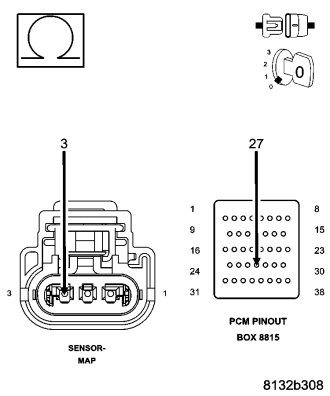
CAUTION: Do not probe the PCM harness connectors. Probing the PCM harness connectors will damage the PCM terminals resulting in poor terminal to pin connection. Install Miller Special Tool #8815 to perform diagnosis.
Is the resistance below 5.0 ohms?
Yes
- Go To 12
No
- Repair the excessive resistance in the (F856) 5-volt Supply circuit.
- Perform the POWERTRAIN VERIFICATION TEST. (Refer to 9 - ENGINE - STANDARD PROCEDURE)
12.(F856) 5-VOLT SUPPLY CIRCUIT SHORTED TO GROUND
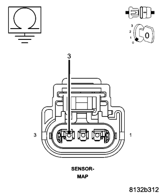
Is the resistance above 100k ohms?
Yes
- Go To 13
No
- Repair the short to ground in the (F856) 5-volt Supply circuit.
- Perform the POWERTRAIN VERIFICATION TEST. (Refer to 9 - ENGINE - STANDARD PROCEDURE)
13.MAP SENSOR
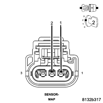
Does the scan tool display MAP voltage from approximately 4.9 volts to below 0.5 of a volt with the jumper wire installed?
Yes
- Replace the MAP Sensor.
- Perform the POWERTRAIN VERIFICATION TEST. (Refer to 9 - ENGINE - STANDARD PROCEDURE)
No
- Go To 14
NOTE: Remove the jumper wire before continuing.
14.EXCESSIVE RESISTANCE IN THE (K1) MAP SIGNAL CIRCUIT
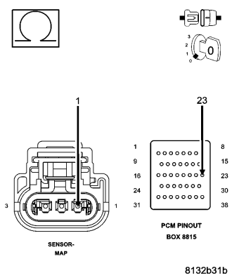
CAUTION: Do not probe the PCM harness connectors. Probing the PCM harness connectors will damage the PCM terminals resulting in poor terminal to pin connection. Install Miller Special Tool #8815 to perform diagnosis.
Is the resistance below 5.0 ohms?
Yes
- Go To 15
No
- Repair the excessive resistance in the (K1) MAP Signal circuit
- Perform the POWERTRAIN VERIFICATION TEST. (Refer to 9 - ENGINE - STANDARD PROCEDURE)
15.(K1) MAP SIGNAL CIRCUIT SHORTED TO GROUND
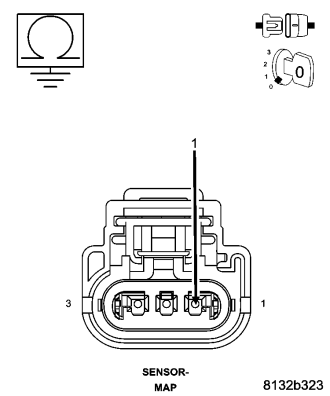
Is the resistance below 100 ohms?
Yes
- Repair the short to ground in the (K1) MAP Signal circuit.
- Perform the POWERTRAIN VERIFICATION TEST. (Refer to 9 - ENGINE - STANDARD PROCEDURE)
No
16
16.EXCESSIVE RESISTANCE IN THE (K900) SENSOR GROUND CIRCUIT
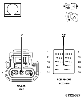
CAUTION: Do not probe the PCM harness connectors. Probing the PCM harness connectors will damage the PCM terminals resulting in poor terminal to pin connection. Install Miller Special Tool #8815 to perform diagnosis.
Is the resistance below 5.0 ohms?
Yes
- Go To 17
No
- Repair the excessive resistance in the (K900) Sensor ground circuit.
- Perform the POWERTRAIN VERIFICATION TEST. (Refer to 9 - ENGINE - STANDARD PROCEDURE)
17.PCM
NOTE: Before continuing, check the PCM harness connector terminals for corrosion, damage, or terminal push out. Repair as necessary.
Were there any problems found?
Yes
- Repair as necessary.
- Perform the POWERTRAIN VERIFICATION TEST. (Refer to 9 - ENGINE - STANDARD PROCEDURE)
No
- Replace and program the Powertrain Control Module per Service Information.
- Perform the POWERTRAIN VERIFICATION TEST. (Refer to 9 - ENGINE - STANDARD PROCEDURE)