ESP/TCS SWITCH CIRCUIT
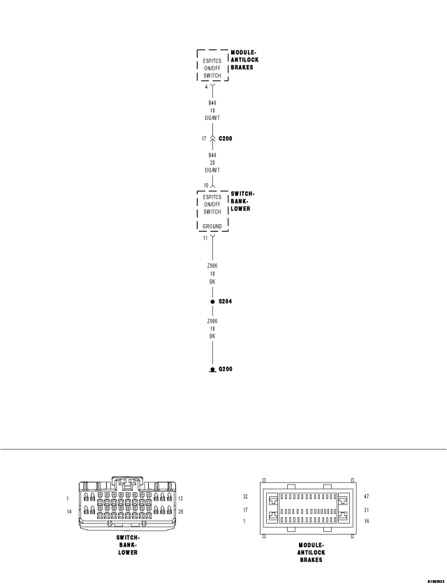
For a complete wiring diagram Refer to Section 8W.
- When Monitored:
With the ignition on.
- Set Condition:
When the Anti-Lock Brake Module indicates that the ESP/TCS Switch is low for 30 seconds.
| Possible Causes |
| STUCK CLOSED ESP/TCS SWITCH |
| (Z906) GROUND CIRCUIT OPEN |
| (B46) ESP/TCS CONTROL SWITCH SENSE CIRCUIT SHORTED TO GROUND |
| ANTI-LOCK BRAKE MODULE |
Diagnostic Test
1.ESP/TCS SWITCH CIRCUITNOTE: If any other DTCs are present they must be repaired before continuing.
Does the scan tool display switch state indicating pressed?
Yes
- Go To 2
No
- The condition that caused the symptom is currently not present. Inspect the related wiring for a possible intermittent condition. Look for any chafed, pierced, pinched, or partially broken wires.
- Refer to the ABS-INTERMITTENT CONDITION TEST. (Refer to 5 - BRAKES - DIAGNOSIS AND TESTING).
2.(Z906) OPEN CIRCUIT
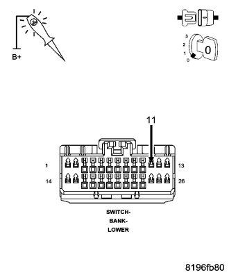
Does the test light illuminate brightly?
Yes
- Go To 3
No
- Repair (Z906) ground circuit for an open circuit or high resistance.
- Perform ABS VERIFICATION TEST. (Refer to 5 - BRAKES - STANDARD PROCEDURE).
3.CHECK FOR A STUCK ESP/TCS SWITCH
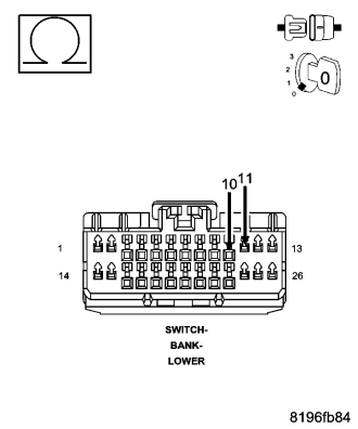
Is the resistance below 5.0 ohms?
Yes
- Replace the ESP/TCS Switch in accordance with the Service Information.
- Perform ABS VERIFICATION TEST. (Refer to 5 - BRAKES - STANDARD PROCEDURE).
No
- Go To 4
4.ESP/TCS CONTROL CIRCUIT
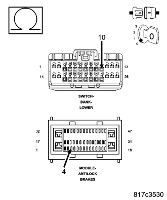
Is the resistance below 5.0 ohms?
Yes
- Repair the (B46) ESP/TCS control circuit for a short to ground.
- Perform ABS VERIFICATION TEST. (Refer to 5 - BRAKES - STANDARD PROCEDURE).
No
- Replace the Anti-Lock Brake Module in accordance with the Service Information.
- Perform ABS VERIFICATION TEST. (Refer to 5 - BRAKES - STANDARD PROCEDURE).