C2116-ABS PUMP MOTOR SUPPLY LOW VOLTAGE
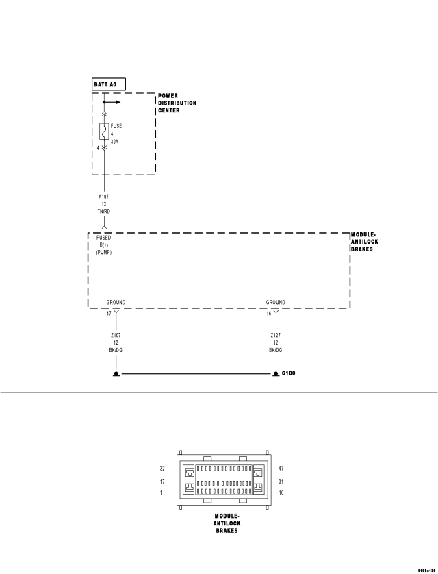
For a complete wiring diagram Refer to Section 8W.
- When Monitored:
With the ignition on.
- Set Condition:
When the Anti-Lock Brake Module indicates the ABS Pump Motor circuit fails the diagnostic test.
| Possible Causes |
| WIRING HARNESS, TERMINAL, CONNECTOR DAMAGE |
| ABS PUMP MOTOR FUSE OPEN |
| (A107) FUSED B(+) CIRCUIT SHORTED TO GROUND OR OPEN |
| GROUND CIRCUIT(S) OPEN OR HIGH RESISTANCE |
| ANTI-LOCK BRAKE MODULE |
Diagnostic Test
1.CHECK FOR A DTC C2116-ABS PUMP MOTOR SUPPLY LOW VOLTAGENOTE: This DTC must be active for the results of this test to be valid.
CAUTION: Ensure braking capability is available before road testing.
Does the scan tool display: C2116-ABS PUMP MOTOR SUPPLY LOW VOLTAGE?
Yes
- Go To 2
No
- Refer to the INTERMITTENT CONDITION diagnostic procedure.
- Refer to the ABS-INTERMITTENT CONDITION TEST. (Refer to 5 - BRAKES - DIAGNOSIS AND TESTING)
2.CHECK ABS PUMP OPERATION WITH SCAN TOOL
Did the ABS Pump Motor operate?
Yes
- Refer to the INTERMITTENT CONDITION diagnostic procedure.
- Perform ABS VERIFICATION TEST. (Refer to 5 - BRAKES - STANDARD PROCEDURE).
No
- Go To 3
3.CHECK THE ABS PUMP MOTOR FUSE FOR AN OPEN
Is the ABS Pump Motor fuse open?
Yes
- Go To 4
No
- Go To 5
4.CHECK THE (A107) FUSED B(+) FOR A SHORT TO GROUND
Is the (A107) Fused B(+) circuit in the wiring harness OK?
Yes
- Go To 5
No
- Repair the (A107) Fused B(+) circuit as necessary. Replace the fuse.
- Perform ABS VERIFICATION TEST. (Refer to 5 - BRAKES - STANDARD PROCEDURE).
5.CHECK THE WIRING HARNESS, TERMINALS, AND CONNECTORS
NOTE: Check all related wiring for bruised, chafed, pierced, or partially broken wires. Check all related connectors for broken, bent, pushed out, or corroded terminals.
Were any problems found?
Yes
- Repair as necessary.
- Perform ABS VERIFICATION TEST. (Refer to 5 - BRAKES - STANDARD PROCEDURE).
No
- Go To 6
6.(A107) FUSED B(+) CIRCUIT OPEN
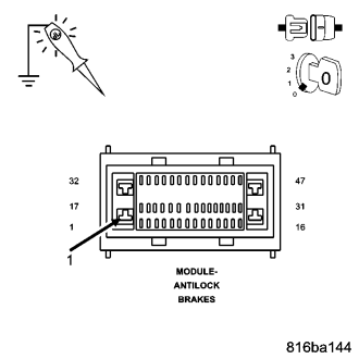
NOTE: The test light should be illuminated and bright. Compare the brightness to that of a direct connection to the battery.
Is the test light illuminated and bright?
Yes
- Go To 7
No
- Repair the (A107) Fused B(+) circuit for an open circuit or high resistance.
- Perform ABS VERIFICATION TEST. (Refer to 5 - BRAKES - STANDARD PROCEDURE).
7.GROUND CIRCUIT(S) OPEN OR HIGH RESISTANCE
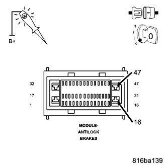
NOTE: The test light should be illuminated and bright. Compare the brightness to that of a direct connection to the battery.
Is the test light illuminated and bright?
Yes
- Replace the Anti-Lock Brake Module in accordance with the Service Information.
- Perform ABS VERIFICATION TEST. (Refer to 5 - BRAKES - STANDARD PROCEDURE).
No
- Repair the Ground circuit(s) for an open circuit or high resistance.
- Perform ABS VERIFICATION TEST. (Refer to 5 - BRAKES - STANDARD PROCEDURE).