33–A/C MODE SWITCH STUCK (MTC)
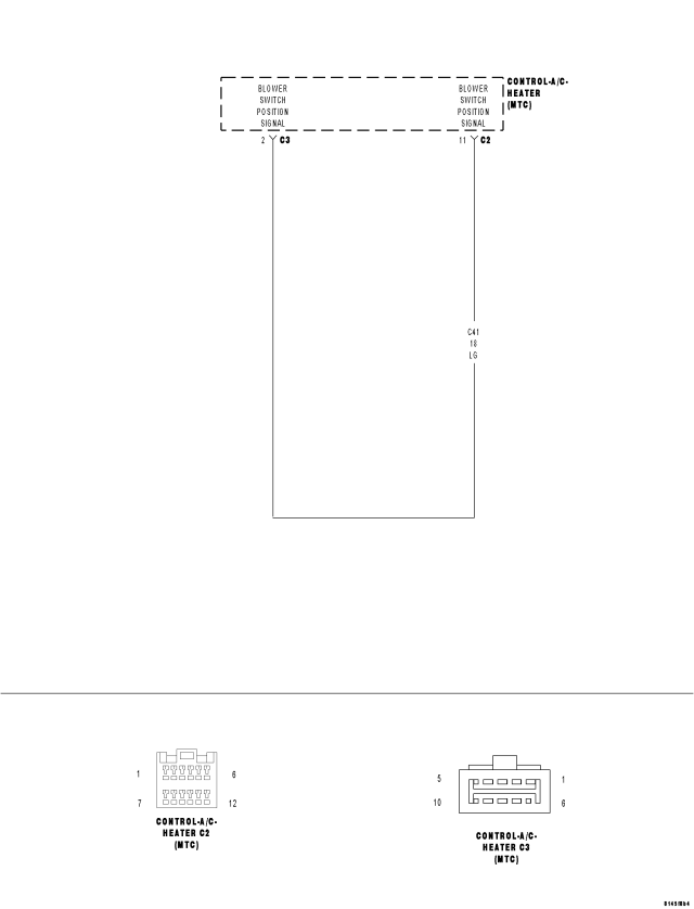
For a complete wiring diagram Refer to Section 8W.
Theory of Operation
The switch input changes when the switch is pushed down. A stored DTC 33 indicates that the A/C mode switch was stuck in a pushed position for more than 10 minutes, but has since returned to its normal state. An active DTC 33 indicates that the A/C mode switch is stuck in a pushed position. An active DTC 33 will prevent the control from entering diagnostic mode and performing certain diagnostic functions. It will also prevent proper A/C mode switch and status indicator function. For additional information about the A/C Heater Control's on-board diagnostics, refer to 24 - HEATING & AIR CONDITIONING - DIAGNOSIS AND TESTING.
- When Monitored:
With the ignition on.
- Set Condition:
If the A/C mode switch stays in a pushed position for more than 10 minutes.
| Possible Causes |
| OBJECT HOLDING A/C MODE SWITCH IN A PUSHED POSITION |
| SUBSTANCE CAUSING A/C MODE SWITCH TO GET STUCK IN A PUSHED POSITION |
| (C41) BLOWER SWITCH POSITION SIGNAL CIRCUIT SHORTED TO VOLTAGE |
| (C41) BLOWER SWITCH POSITION SIGNAL CIRCUIT SHORTED TO (C121) SENSOR GROUND CIRCUIT |
| (C41) BLOWER SWITCH POSITION SIGNAL CIRCUIT SHORTED TO GROUND |
| (C41) BLOWER SWITCH POSITION SIGNAL CIRCUIT OPEN |
| A/C STATUS INDICATOR INOPERATIVE |
| A/C HEATER CONTROL |
Diagnostic Test
1.INSPECT THE A/C HEATER CONTROL FOR DAMAGEIs the A/C Heater Control damaged?
Yes
- Replace the A/C Heater Control in accordance with the Service Information.
- Perform BODY VERIFICATION TEST – VER 1. (Refer to 8 - ELECTRICAL/ELECTRONIC CONTROL MODULES - STANDARD PROCEDURE).
No
- Go To 2
2.INSPECT FOR OBJECT OR SUBSTANCE CAUSING THE A/C MODE SWITCH TO STAY OR STICK IN A PUSHED POSITION
Is anything present that would cause the A/C mode switch to stay or stick in a pushed position?
Yes
- Repair as necessary.
- Perform BODY VERIFICATION TEST – VER 1. (Refer to 8 - ELECTRICAL/ELECTRONIC CONTROL MODULES - STANDARD PROCEDURE).
No
- Go To 3
3.CHECK THE (C41) BLOWER SWITCH POSITION SIGNAL CIRCUIT VOLTAGE
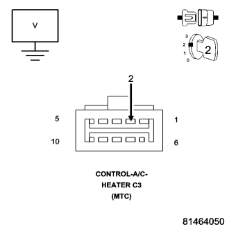
What is the voltage?
Below 4.8 Volts
- Go To 4
Above 5.2 Volts
- Go To 7
4.8 Volts To 5.2 Volts
- Go To 8
4.CHECK THE (C41) BLOWER SWITCH POSITION SIGNAL CIRCUIT FOR A SHORT TO THE (C121) SENSOR GROUND CIRCUIT
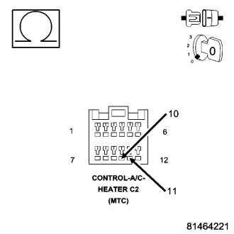
Is the resistance below 10K ohms?
Yes
- Repair the (C41) Blower Switch Position Signal circuit for a short to the (C121) Sensor Ground circuit.
- Perform BODY VERIFICATION TEST - VER 1. (Refer to 8 - ELECTRICAL/ELECTRONIC CONTROL MODULES - STANDARD PROCEDURE).
No
- Go To 5
5.CHECK THE (C41) BLOWER SWITCH POSITION SIGNAL CIRCUIT FOR A SHORT TO GROUND
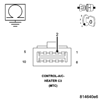
Is the resistance below 10K ohms?
Yes
- Repair the (C41) Blower Switch Position Signal circuit for a short to ground.
- Perform BODY VERIFICATION TEST - VER 1. (Refer to 8 - ELECTRICAL/ELECTRONIC CONTROL MODULES - STANDARD PROCEDURE).
No
- Go To 6
6.CHECK (C41) BLOWER SWITCH POSITION SIGNAL CIRCUIT FOR AN OPEN
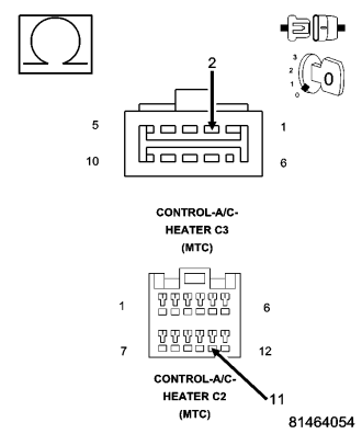
Is the resistance below 5.0 ohms?
Yes
- Replace the A/C Heater Control in accordance with the Service Information.
- Perform BODY VERIFICATION TEST - VER 1. (Refer to 8 - ELECTRICAL/ELECTRONIC CONTROL MODULES - STANDARD PROCEDURE).
No
- Repair the (C41) Blower Switch Position Signal circuit for an open.
- Perform BODY VERIFICATION TEST - VER 1. (Refer to 8 - ELECTRICAL/ELECTRONIC CONTROL MODULES - STANDARD PROCEDURE).
7.CHECK THE (C41) BLOWER SWITCH POSITION SIGNAL CIRCUIT FOR A SHORT TO VOLTAGE
Is the voltage above 0.2 volts?
Yes
- Repair the (C41) Blower Switch Position Signal circuit for a short to voltage.
- Perform BODY VERIFICATION TEST - VER 1. (Refer to 8 - ELECTRICAL/ELECTRONIC CONTROL MODULES - STANDARD PROCEDURE).
No
- Replace the A/C Heater Control in accordance with the Service Information.
- Perform BODY VERIFICATION TEST - VER 1. (Refer to 8 - ELECTRICAL/ELECTRONIC CONTROL MODULES - STANDARD PROCEDURE).
8.CHECK FOR NORMAL A/C MODE SWITCH & STATUS INDICATOR FUNCTION
Does the A/C status indicator turn on and off with respect to the switch position?
Yes
- Go To 9
No
- Replace the A/C Heater Control in accordance with the Service Information.
- Perform BODY VERIFICATION TEST – VER 1. (Refer to 8 - ELECTRICAL/ELECTRONIC CONTROL MODULES - STANDARD PROCEDURE).
9.CHECK A/C HEATER CONTROL OPERATION BY ATTEMPTING TO ENTER DIAGNOSTIC MODE
- Turn the blower control on.
- Press the A/C mode switch down, turn the blower control to off, wait until both LEDs illuminate (approximately 5 seconds) and then release the A/C mode switch.
Did the A/C Heater Control enter diagnostic mode?
Yes
- Perform BODY VERIFICATION TEST – VER 1. (Refer to 8 - ELECTRICAL/ELECTRONIC CONTROL MODULES - STANDARD PROCEDURE).
No
- Replace the A/C Heater Control in accordance with the Service Information.
- Perform BODY VERIFICATION TEST – VER 1. (Refer to 8 - ELECTRICAL/ELECTRONIC CONTROL MODULES - STANDARD PROCEDURE).