P0720-OUTPUT SPEED SENSOR CIRCUIT
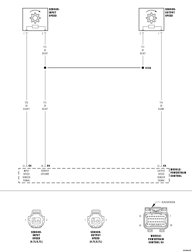
For a complete wiring diagram Refer to Section 8W.
Theory of Operation
The transmission system uses two speed sensors, one to measure input RPM and one to measure output RPM. These inputs are essential for proper transmission operation. Therefore, the integrity of this data is verified through the following checks:
- When in gear, if the gear ratio does not compare to a known gear ratio, the corresponding in-gear trouble code is set (codes P0731-36 and P1736).
- An excessive change in input or output speeds indicating signal intermittent will result in codes P0715 and/or P0720 being set.
- If the common speed sensor ground circuit is lost, both sensor inputs will read the signal from the input speed sensor at idle in neutral. Since the input speed sensor has 60 teeth and the output speed sensor has 30 teeth, this results in a an apparent speed ratio of 1:2 and may cause the DTC P1794 to set.
- When Monitored:
The transmission gear ratio is monitored continuously while the transmission is in gear.
- Set Condition:
If there is an excessive change in output RPM in any gear. This DTC can take up to five minutes of problem identification before illuminating the MIL.
| Possible Causes |
| OUTPUT SPEED SENSOR SIGNAL CIRCUIT OPEN |
| SPEED SENSOR GROUND CIRCUIT OPEN |
| OUTPUT SPEED SENSOR SIGNAL CIRCUIT SHORT TO GROUND |
| SPEED SENSOR GROUND CIRCUIT SHORT TO GROUND |
| OUTPUT SPEED SENSOR SIGNAL CIRCUIT SHORT TO VOLTAGE |
| SPEED SENSOR GROUND CIRCUIT SHORT TO VOLTAGE |
| OUTPUT SPEED SENSOR |
| POWERTRAIN CONTROL MODULE |
Always perform the 45RFE/545RFE Pre-Diagnostic Troubleshooting procedure before proceeding. (Refer to 21 - TRANSMISSION/TRANSAXLE/AUTOMATIC - 45RFE/545RFE - STANDARD PROCEDURE)
Diagnostic Test
1.CHECK IF DTC P0720 IS CURRENTCAUTION: Properly support the vehicle and raise all drive wheels off the ground.
WARNING: Be sure to keep hands and feet clear of rotating wheels.
Is the Output Speed Sensor RPM below 100 RPM?
Yes
- Go To 2
No
- Go To 9
2.CHECK THE OUTPUT SPEED SENSOR
CAUTION: Removal of the Starter Relay will prevent the vehicle from being started in gear.
WARNING: The Starter Relay must be removed from the PDC. Failure to do so can result in personal injury or death.
NOTE: Failure to remove the Starter Relay can cause a Transmission - No Response condition.
Does the Input Speed read 3000 rpm and the Output Speed read 1000 rpm (± 50 rpm)?
Yes
- Replace the Output Speed Sensor per the Service Information.
- Perform 45RFE/545RFE TRANSMISSION VERIFICATION TEST. (Refer to 21 - TRANSMISSION/TRANSAXLE/AUTOMATIC - 45RFE/545RFE - STANDARD PROCEDURE)
No
- Go To 3
3.CHECK THE (T14) OUTPUT SPEED SENSOR SIGNAL CIRCUIT FOR AN OPEN
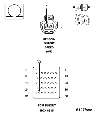
CAUTION: Do not probe the PCM harness connectors. Probing the PCM harness connectors will damage the PCM terminals resulting in poor terminal to pin connection. Install Miller tool #8815 to perform diagnosis.
Is the resistance above 5.0 ohms?
Yes
- Repair the (T14) Output Speed Sensor Signal circuit for an open.
- Perform 45RFE/545RFE TRANSMISSION VERIFICATION TEST. (Refer to 21 - TRANSMISSION/TRANSAXLE/AUTOMATIC - 45RFE/545RFE - STANDARD PROCEDURE)
No
- Go To 4
4.CHECK THE (T13) SPEED SENSOR GROUND CIRCUIT FOR AN OPEN
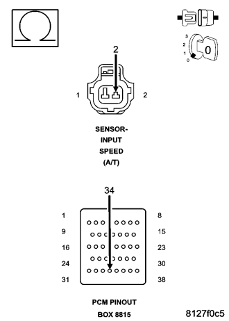
Is the resistance above 5.0 ohms?
Yes
- Repair the (T13) Speed Sensor Ground circuit for an open.
- Perform 45RFE/545RFE TRANSMISSION VERIFICATION TEST. (Refer to 21 - TRANSMISSION/TRANSAXLE/AUTOMATIC - 45RFE/545RFE - STANDARD PROCEDURE)
No
- Go To 5
5.CHECK THE (T14) OUTPUT SPEED SENSOR SIGNAL CIRCUIT FOR A SHORT TO GROUND
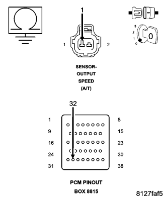
Is the resistance below 5.0 ohms?
Yes
- Repair the (T14) Output Speed Sensor Signal circuit for a short to ground.
- Perform 45RFE/545RFE TRANSMISSION VERIFICATION TEST. (Refer to 21 - TRANSMISSION/TRANSAXLE/AUTOMATIC - 45RFE/545RFE - STANDARD PROCEDURE)
No
- Go To 6
6.CHECK THE (T13) SPEED SENSOR GROUND CIRCUIT FOR A SHORT TO GROUND
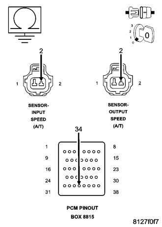
Is the resistance below 5.0 ohms?
Yes
- Repair the (T13) Speed Sensor Ground circuit for a short to ground.
- Perform 45RFE/545RFE TRANSMISSION VERIFICATION TEST. (Refer to 21 - TRANSMISSION/TRANSAXLE/AUTOMATIC - 45RFE/545RFE - STANDARD PROCEDURE)
No
- Go To 7
7.CHECK THE (T14) OUTPUT SPEED SENSOR SIGNAL CIRCUIT FOR A SHORT TO VOLTAGE
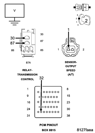
Is the voltage above 0.5 volts?
Yes
- Repair the (T14) Output Speed Sensor Signal circuit for a short to voltage.
- Perform 45RFE/545RFE TRANSMISSION VERIFICATION TEST. (Refer to 21 - TRANSMISSION/TRANSAXLE/AUTOMATIC - 45RFE/545RFE - STANDARD PROCEDURE)
No
- Go To 8
8.CHECK THE (T13) SPEED SENSOR GROUND CIRCUIT FOR A SHORT TO VOLTAGE
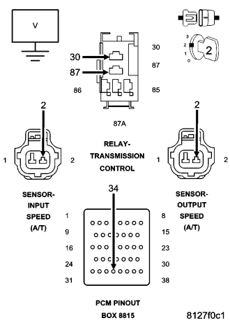
Is the voltage above 0.5 volts?
Yes
- Repair the (T13) Speed Sensor Ground circuit for a short to voltage.
- Perform 45RFE/545RFE TRANSMISSION VERIFICATION TEST. (Refer to 21 - TRANSMISSION/TRANSAXLE/AUTOMATIC - 45RFE/545RFE - STANDARD PROCEDURE)
No
- Using the schematics as a guide, check the Powertrain Control Module (PCM) terminals for corrosion, damage, or terminal push out. Pay particular attention to all power and ground circuits. If no problems are found, replace the PCM per the Service Information. With the scan tool, perform QUICK LEARN.
- Perform 45RFE/545RFE TRANSMISSION VERIFICATION TEST. (Refer to 21 - TRANSMISSION/TRANSAXLE/AUTOMATIC - 45RFE/545RFE - STANDARD PROCEDURE)
9.CHECK WIRING AND CONNECTORS
Were there any problems found?
Yes
- Repair as necessary.
- Perform 45RFE/545RFE TRANSMISSION VERIFICATION TEST. (Refer to 21 - TRANSMISSION/TRANSAXLE/AUTOMATIC - 45RFE/545RFE - STANDARD PROCEDURE)
No
- Test Complete.