P0706-TRANSMISSION RANGE SENSOR RATIONALITY
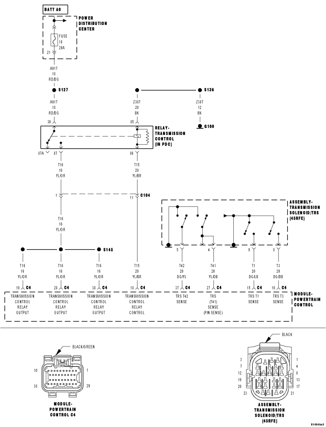
For a complete wiring diagram Refer to Section 8W.
Theory of Operation
The T41 (C1) T42 (C2), T3 (C3), T1 (C4), or T2 (C5) Sense circuits communicate the shift lever position to the Transmission Control System. Each circuit is terminated at the transmission by a switch (TRS). Each switch can be either open or closed, depending on the shift lever position. The PCM can decode this information and determine the shift lever position.
Each shift lever position has it own unique combination of closed and open switches. This is called a PRNDL code. There are 5 switches, therefore: there are many possible combinations of open and closed switches (codes). There are 12 valid codes: two for neutral, one for each other gear position (5), and five temporary (transition zone) codes. The remainder of the codes should never occur, these are called invalid codes.
- When Monitored:
Continuously with the ignition on.
- Set Condition:
The DTC will set if the controller detects an invalid PRNDL code which lasts for more than 0.042 seconds.
| Possible Causes |
| SHIFTER OUT OF ADJUSTMENT |
| TRS SENSE CIRCUIT OPEN |
| TRS SENSE CIRCUIT SHORT TO GROUND |
| TRS SENSE CIRCUIT SHORT TO VOLTAGE |
| METAL DEBRIS IN OIL PAN |
| TRANSMISSION RANGE SENSOR |
| POWERTRAIN CONTROL MODULE |
Always perform the 45RFE/545RFE Pre-Diagnostic Troubleshooting procedure before proceeding. (Refer to 21 - TRANSMISSION/TRANSAXLE/AUTOMATIC - 45RFE/545RFE - STANDARD PROCEDURE)
Diagnostic Test
1.CHECK IF P0706 DTC IS CURRENTSelect the test outcome from the following:
Test passes:
- Go To 6
Test fails with Error Code:
- Go To 2
Test fails without Error Code:
- Perform the Gearshift Adjustment Procedure per the Service Information.
- Perform 45RFE/545RFE TRANSMISSION VERIFICATION TEST. (Refer to 21 - TRANSMISSION/TRANSAXLE/AUTOMATIC - 45RFE/545RFE - STANDARD PROCEDURE)
2.CHECK THE TRANSMISSION SOLENOID/TRS ASSEMBLY
CAUTION: Removal of the Starter Relay will prevent the vehicle from being started in gear.
WARNING: The Starter Relay must be removed from the PDC. Failure to do so can result in personal injury or death.
NOTE: Failure to remove the Starter Relay can cause a Transmission - No Response condition.
NOTE: When the scan tool requests the O/D off button be depressed, you must use the O/D OFF button in the vehicle or you will fail the Shift Lever Position Test with an error code 11 or OD-TOW/HALL STUCK OPEN.
NOTE: If the Shift Lever Position test fails, make sure to note the identification of the TRS Sense circuit for future reference.
Did the Shift Lever Position test pass?
Yes
- Remove the Oil Pan and Main Valve Body Assembly per the Service Information. Check for metal debris on top of the Solenoid/TRS Assembly and the manual valve code plate. If debris is present, determine the cause of the debris and repair the transmission as necessary. If no problems are found, replace the Transmission Solenoid/TRS Assembly per the Service Information.
- Perform 45RFE/545RFE TRANSMISSION VERIFICATION TEST. (Refer to 21 - TRANSMISSION/TRANSAXLE/AUTOMATIC - 45RFE/545RFE - STANDARD PROCEDURE)
No
- Go To 3
3.CHECK THE TRS SENSE CIRCUITS FOR AN OPEN
CAUTION: Do not probe the PCM harness connectors. Probing the PCM harness connectors will damage the PCM terminals resulting in poor terminal to pin connection. Install Miller tool #8815 to perform diagnosis.
Is the resistance above 5.0 ohms?
Yes
- Repair the identified T41, T42, T3, T1, or T2 (C1-C5) TRS Sense circuit for an open.
- Perform 45RFE/545RFE TRANSMISSION VERIFICATION TEST. (Refer to 21 - TRANSMISSION/TRANSAXLE/AUTOMATIC - 45RFE/545RFE - STANDARD PROCEDURE)
No
- Go To 4
4.CHECK THE TRS SENSE CIRCUITS FOR A SHORT TO GROUND
Is the resistance below 5.0 ohms?
Yes
- Repair the identified T1, T2, T3, T41, or T42 (C1-C5) TRS Sense circuit for a short to ground.
- Perform 45RFE/545RFE TRANSMISSION VERIFICATION TEST. (Refer to 21 - TRANSMISSION/TRANSAXLE/AUTOMATIC - 45RFE/545RFE - STANDARD PROCEDURE)
No
- Go To 5
5.CHECK THE TRS SENSE CIRCUITS FOR A SHORT TO ANOTHER CIRCUIT
Is the resistance below 100k ohms between the identified T1, T2, T3, T41, or T42 (C1-C5) TRS Sense circuit and any other circuit(s) in the Transmission Solenoid/TRS Assembly harness connector?
Yes
- Repair the identified T1, T2, T3, T41, or T42 (C1-C5) TRS Sense circuit for a short to another circuit(s).
- Perform 45RFE/545RFE TRANSMISSION VERIFICATION TEST.
No
- Using the schematics as a guide, check the Powertrain Control Module (PCM) terminals for corrosion, damage, or terminal push out. Pay particular attention to all power and ground circuits. If no problems are found, replace the PCM per the Service Information. With the scan tool, perform QUICK LEARN.
- Perform 45RFE/545RFE TRANSMISSION VERIFICATION TEST. (Refer to 21 - TRANSMISSION/TRANSAXLE/AUTOMATIC - 45RFE/545RFE - STANDARD PROCEDURE)
6.CHECK WIRING AND CONNECTORS
Were there any problems found?
Yes
- Repair as necessary.
- Perform 45RFE/545RFE TRANSMISSION VERIFICATION TEST. (Refer to 21 - TRANSMISSION/TRANSAXLE/AUTOMATIC - 45RFE/545RFE - STANDARD PROCEDURE)
No
- Test Complete.