P0591-SPEED CONTROL SWITCH 2 PERFORMANCE
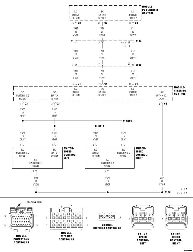
For a complete wiring diagram Refer to Section 8W.
- When Monitored:
With the ignition key on.
- Set Condition:
Cruise switch voltage output is not out of range but it does not equal any of the values for any of the button positions. One trip fault.
| Possible Causes |
| (V372) S/C SWITCH NO.2 SIGNAL CIRCUIT OPEN |
| (V72) S/C SWITCH NO.2 SIGNAL CIRCUIT OPEN |
| (V372) S/C SWITCH NO.2 SIGNAL CIRCUIT SHORTED TO BATTERY VOLTAGE |
| (V72) S/C SWITCH NO.2 SIGNAL CIRCUIT SHORTED TO BATTERY VOLTAGE |
| (V397) SWITCH RETURN CIRCUIT OPEN |
| (V937) SWITCH RETURN CIRCUIT OPEN |
| (V372) S/C SWITCH NO.2 SIGNAL CIRCUIT SHORTED TO GROUND |
| (V72) S/C SWITCH NO.2 SIGNAL CIRCUIT SHORTED TO GROUND |
| (V372) S/C SWITCH NO.2 SIGNAL CIRCUIT SHORTED TO THE (V397) SWITCH RETURN CIRCUIT |
| (V72) S/C SWITCH NO.2 SIGNAL CIRCUIT SHORTED TO THE (V937) SWITCH RETURN CIRCUIT |
| SPEED CONTROL SWITCH |
| SCCM |
| PCM |
Always perform the Pre-Diagnostic Troubleshooting procedure before proceeding. (Refer to 9 - ENGINE - DIAGNOSIS AND TESTING).
Diagnostic Test
1.SPEED CONTROL SWITCH STATUSDoes each switch function change status when pressing and then depressing each switch?
Yes
- Refer to the INTERMITTENT CONDITION Diagnostic Procedure.
- Perform the POWERTRAIN VERIFICATION TEST. (Refer to 9 - ENGINE - STANDARD PROCEDURE)
No
- Go To 2
2.SPEED CONTROL SWITCHES
Does the function on the Speed Control Switches have the correct resistance value?
Yes
- Go To 3
No
- Replace the Speed Control Switch that had the incorrect resistance value.
- Perform the POWERTRAIN VERIFICATION TEST. (Refer to 9 - ENGINE - STANDARD PROCEDURE)
3.(V372) S/C SWITCH NO.2 SIGNAL CIRCUIT SHORTED TO BATTERY VOLTAGE
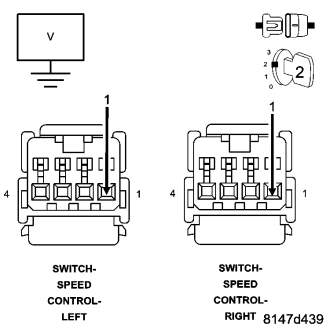
Is the voltage above 0 volts?
Yes
- Repair the short to battery voltage in the (V372) S/C Switch No.2 Signal circuit.
- Perform the POWERTRAIN VERIFICATION TEST. (Refer to 9 - ENGINE - STANDARD PROCEDURE)
No
- Go To 4
4.(V72) S/C SWITCH NO.2 SIGNAL CIRCUIT SHORTED TO BATTERY VOLTAGE
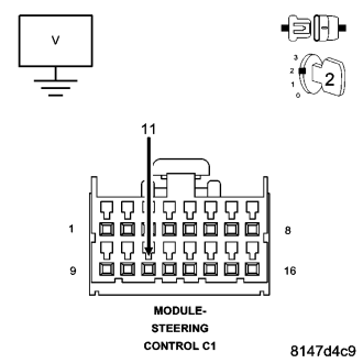
Is the voltage above 0 volts?
Yes
- Repair the short to battery voltage in the (V72) S/C Switch No.2 Signal circuit.
- Perform the POWERTRAIN VERIFICATION TEST. (Refer to 9 - ENGINE - STANDARD PROCEDURE)
No
- Go To 5
5.STEERING COLUMN CONTROL MODULE
Is the resistance above 5.0 ohms?
Yes
- Replace the Steering Column Control Module per Service Information.
- Perform the POWERTRAIN VERIFICATION TEST. (Refer to 9 - ENGINE - STANDARD PROCEDURE)
No
- Go To 6
6.(V372) S/C SWITCH NO.2 SIGNAL CIRCUIT OPEN
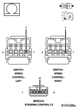
NOTE: The measurement must be taken from both Speed Control Switch harness connectors.
Is the resistance below 5.0 ohms for both measurements?
Yes
- Go To 7
No
- Repair the open in the (V372) S/C Switch No.2 Signal circuit.
- Perform the POWERTRAIN VERIFICATION TEST. (Refer to 9 - ENGINE - STANDARD PROCEDURE)
7.(V72) S/C SWITCH NO.2 SIGNAL CIRCUIT OPEN
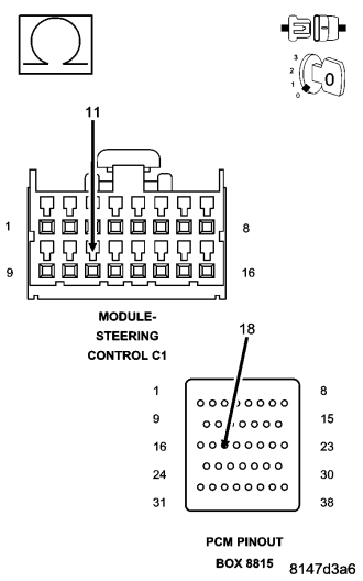
CAUTION: Do not probe the PCM harness connectors. Probing the PCM harness connectors will damage the PCM terminals resulting in poor terminal to pin connection. Install Miller Special Tool #8815 to perform diagnosis.
Is the resistance below 5.0 ohms for both measurements?
Yes
- Go To 8
No
- Repair the open in the (V72) S/C Switch No.2 Signal circuit.
- Perform the POWERTRAIN VERIFICATION TEST. (Refer to 9 - ENGINE - STANDARD PROCEDURE)
8.(V397) SWITCH RETURN CIRCUIT OPEN
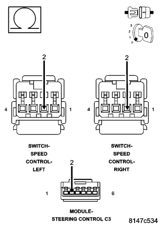
Is the resistance below 5.0 ohms for both measurements?
Yes
- Go To 9
No
- Repair the open in the (V397) Switch Return circuit.
- Perform the POWERTRAIN VERIFICATION TEST. (Refer to 9 - ENGINE - STANDARD PROCEDURE)
9.(V937) SWITCH RETURN OPEN
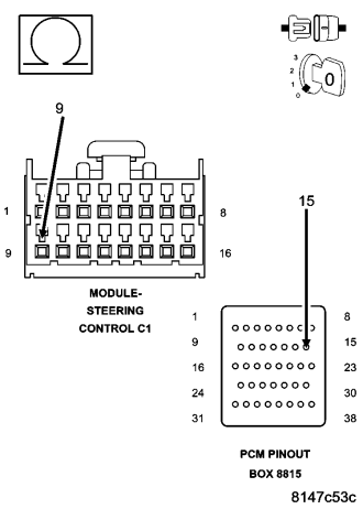
Is the resistance below 5.0 ohms for both measurement?
Yes
- Go To 10
No
- Repair the open in the (V937) Switch Return circuit.
- Perform the POWERTRAIN VERIFICATION TEST. (Refer to 9 - ENGINE - STANDARD PROCEDURE)
10.(V372) S/C SWITCH NO.2 SIGNAL CIRCUIT SHORTED TO GROUND
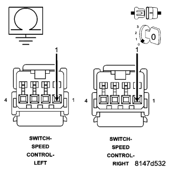
Is the resistance below 100 ohms?
Yes
- Repair the short to ground in the (V372) S/C Switch No.2 Signal circuit.
- Perform the POWERTRAIN VERIFICATION TEST. (Refer to 9 - ENGINE - STANDARD PROCEDURE)
No
- Go To 11
11.(V72) S/C NO.2 SWITCH SIGNAL CIRCUIT SHORTED TO GROUND
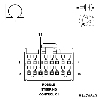
Is the resistance below 100 ohms?
Yes
- Repair the short to ground in the (V72) S/C Switch No.2 Signal circuit.
- Perform the POWERTRAIN VERIFICATION TEST. (Refer to 9 - ENGINE - STANDARD PROCEDURE)
No
- Go To 12
12.(V372) S/C SWITCH NO.2 SIGNAL CIRCUIT SHORTED TO THE (V397) SWITCH RETURN CIRCUIT
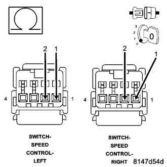
Is the resistance below 5.0 ohms?
Yes
- Repair the short between the (V372) S/C Switch No.2 Signal circuit and the (V397) Switch Return circuit.
- Perform the POWERTRAIN VERIFICATION TEST. (Refer to 9 - ENGINE - STANDARD PROCEDURE)
No
- Go To 13
13.(V72) S/C SWITCH NO.2 SIGNAL CIRCUIT SHORTED TO THE (V937) S/C SWITCH RETURN CIRCUIT
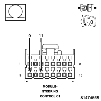
Is the resistance below 5.0 ohms?
Yes
- Repair the short between the (V72) S/C Switch No.2 Signal circuit and the (V937) Switch Return circuit.
- Perform the POWERTRAIN VERIFICATION TEST. (Refer to 9 - ENGINE - STANDARD PROCEDURE)
No
- Go To 14
14.SPEED CONTROL SWITCH VOLTAGE VALUES
| SWITCH POSITION | SWITCH No.1 VOLTAGE VALUE | SWITCH No.2 VOLTAGE VALUE |
| NO SWITCHES PRESSED | 4.31 to 4.78 volts | 4.31 to 4.78 volts |
| ON/OFF PRESSED | 0.59 to 1.13 volts | 3.53 to 3.92 volts |
| RES/ACCEL PRESSED | 3.88 to 4.17 volts | 2.04 to 2.47 volts |
| SET PRESSED | 3.16 to 3.56 volts | 1.17 to 1.56 volts |
| COAST PRESSED | 2.57 to 2.94 volts | 0.77 to 1.09 volts |
| CANCEL PRESSED | 1.59 to 1.99 volts | 2.84 to 3.25 volts |
Are the voltage readings out of the listed specification and is there less than a 0.2 of a volt difference between the voltmeter switch values and the scan tool switch values?
Yes
- Replace the Speed Control Switch.
- Perform the POWERTRAIN VERIFICATION TEST. (Refer to 9 - ENGINE - STANDARD PROCEDURE)
No
- Go To 15
15.PCM
NOTE: Before continuing, check the PCM harness connector terminals for corrosion, damage, or terminal push out. Repair as necessary.
Were there any problems found?
Yes
- Repair as necessary.
- Perform the POWERTRAIN VERIFICATION TEST. (Refer to 9 - ENGINE - STANDARD PROCEDURE)
No
- Replace and program the Powertrain Control Module per Service Information.
- Perform the POWERTRAIN VERIFICATION TEST. (Refer to 9 - ENGINE - STANDARD PROCEDURE)