INSTALLATION
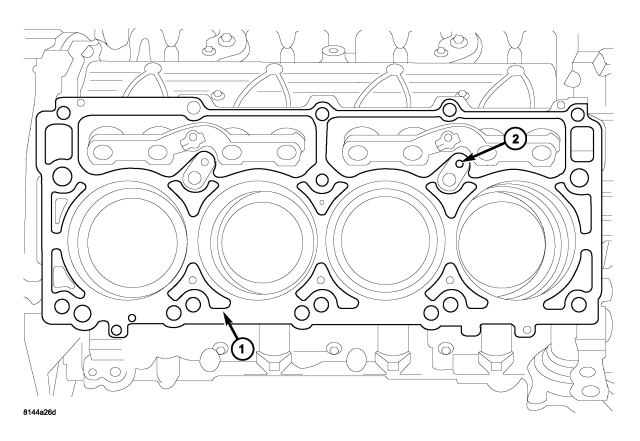
CAUTION: The head gaskets (1) are interchangeable between left and right sides. They are marked “UP” to indicate direction to face up.
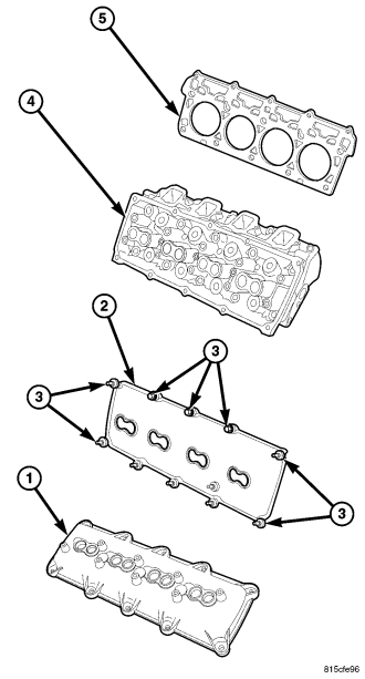
NOTE: Rotate crankshaft @ 45°, so that all pistons are ½ the way down the cylinder bore to avoid piston to valve contact.
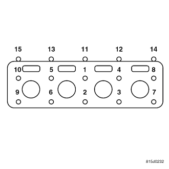
- Step 1— Snug tighten M12 cylinder head bolts, in sequence, to 34 N·m (25 ft. lbs.) and M8 bolts to 20 N·m (15 ft. lbs.) torque.
- Step 2— Tighten M12 cylinder head bolts, in sequence, to 54 N·m (40 ft. lbs.) and verify M8 bolts to 20 N·m (15 ft. lbs.) torque..
- Step 3— Turn M12 cylinder head bolts, in sequence, 90 degrees and tighten M8 bolts to 34 N·m (25 ft. lbs.) torque.
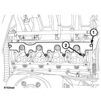
(Refer to 9 - ENGINE/CYLINDER HEAD/ROCKER ARM / ADJUSTER ASSY - INSTALLATION)
(Refer to 9 - ENGINE/MANIFOLDS/INTAKE MANIFOLD - INSTALLATION)
(Refer to 7 - COOLING/ACCESSORY DRIVE/DRIVE BELTS - INSTALLATION)
(Refer to 9 - ENGINE/CYLINDER HEAD/CYLINDER HEAD COVER(S) - INSTALLATION)
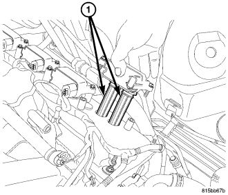
(Refer to 8 - ELECTRICAL/IGNITION CONTROL/IGNITION COIL - INSTALLATION)
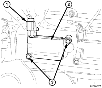
(Refer to 8 - ELECTRICAL/IGNITION CONTROL/IGNITION COIL - INSTALLATION)
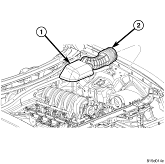
(Refer to 9 - ENGINE/AIR INTAKE SYSTEM - INSTALLATION)
(Refer to 7 - COOLING - STANDARD PROCEDURE)