U0021-CAN B BUS (+) CIRCUIT OPEN
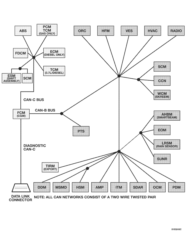
For a complete wiring diagram Refer to Section 8W.
- When Monitored:
With the ignition on and battery voltage between 10 and 16 volts.
- Set Condition:
The FCM detects the (D55) CAN B Bus (+) circuit is open.
| Possible Causes |
| CAN B BUS TERMINAL PUSH OUT |
| SPREAD CAN B BUS TERMINAL |
| (D55) CAN B BUS (+) CIRCUIT OPEN |
| INTERNAL OPEN IN A CAN B BUS MODULE |
Diagnostic Test
1.TEST FOR INTERMITTENT CONDITIONDoes the scan tool display this DTC as active?
Yes
- Go To 2
No
- The conditions that caused this code to set are not present at this time. Using the wiring diagram/schematic as a guide, inspect the wiring and connectors.
2.ATTEMPT TO ISOLATE THE OPEN CONDITION
NOTE: A red X will be next to the module that is not communicating, indicating that the module is not active on the Bus network. A green check indicates that the module is active on the Bus network.
NOTE: If any module is not communicating, perform the appropriate no response test procedure before proceeding.
Are there any red X's displayed next to the modules?
Yes
- Go To 3
No
- Check backprobe connection to ground, make sure it is proper. The CAN B Bus open DTC may no longer be active, it may be stored. Check all module connections
- Perform BODY VERIFICATION TEST – VER 1. (Refer to 8 - ELECTRICAL/ELECTRONIC CONTROL MODULES - STANDARD PROCEDURE).
3.ATTEMPT TO ISOLATE THE OPEN CONDITION — MULTIPLE RED X'S
Are there multiple red X's displayed next to the modules?
Yes
- The most likely cause of this condition is an open CAN B Bus (+) circuit between a common CAN B Bus splice and the modules that display the red X next to them. Use the wiring diagrams will help you determine where open condition exists.
- Perform BODY VERIFICATION TEST – VER 1. (Refer to 8 - ELECTRICAL/ELECTRONIC CONTROL MODULES - STANDARD PROCEDURE).
No
- Go To 4
4.(D55) CAN B BUS (+) CIRCUIT OPEN — SINGLE RED X
Is there any voltage present?
Yes
- Inspect the connector and terminal for damage, inspect for spread terminals, or push out terminals. If ok, replace the module that displayed the red X next to it in accordance with the service information.
- Perform BODY VERIFICATION TEST – VER 1. (Refer to 8 - ELECTRICAL/ELECTRONIC CONTROL MODULES - STANDARD PROCEDURE).
No
- Repair the (D55) CAN B Bus (+) circuit for an open between the next common splice and the module that has the red X displayed next to it. Use the wiring diagrams will help you determine where open condition exists.
- Perform BODY VERIFICATION TEST – VER 1. (Refer to 8 - ELECTRICAL/ELECTRONIC CONTROL MODULES - STANDARD PROCEDURE).