REMOVAL - ENGINE
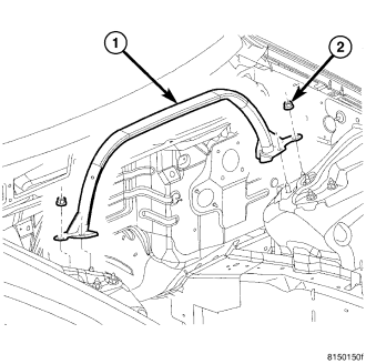
(Refer to 14 - FUEL SYSTEM/FUEL DELIVERY - STANDARD PROCEDURE) (Refer to 14 - FUEL SYSTEM/FUEL DELIVERY/QUICK CONNECT FITTING - STANDARD PROCEDURE)
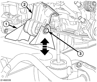
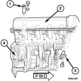
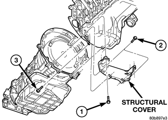
(Refer to 9 - ENGINE/ENGINE BLOCK/STRUCTURAL COVER - REMOVAL)
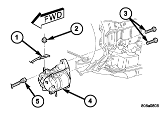
(Refer to 8 - ELECTRICAL/STARTING/STARTER MOTOR - REMOVAL)
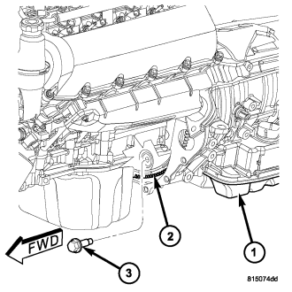
(Refer to 7 - COOLING - STANDARD PROCEDURE)
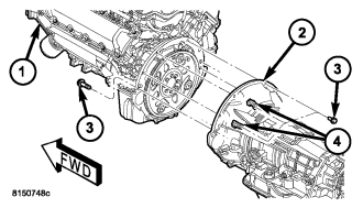
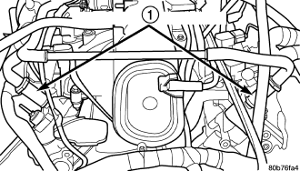
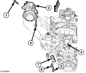
(Refer to 24 - HEATING & AIR CONDITIONING/PLUMBING/REFRIGERANT - STANDARD PROCEDURE)
(Refer to 24 - HEATING & AIR CONDITIONING/PLUMBING/A/C COMPRESSOR - REMOVAL)
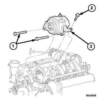
(Refer to 7 - COOLING/ENGINE/FAN DRIVE VISCOUS CLUTCH - REMOVAL) (Refer to 7 - COOLING/ACCESSORY DRIVE/DRIVE BELTS - REMOVAL)
(Refer to 7 - COOLING/ENGINE/RADIATOR - REMOVAL) (Refer to 24 - HEATING & AIR CONDITIONING/PLUMBING/A/C CONDENSER - REMOVAL)
(Refer to 8 - ELECTRICAL/CHARGING/GENERATOR - REMOVAL)
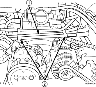
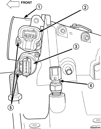
- Intake air temperature (IAT) sensor (4)
- Fuel Injectors
- Throttle Position (TPS) Switch (2)
- Idle Air Control (IAC) Motor (3)
- Engine Oil Pressure Switch
- Engine Coolant Temperature (ECT) Sensor
- Manifold absolute pressure (MAP) Sensor
- Camshaft Position (CMP) Sensor
- Coil Over Plugs
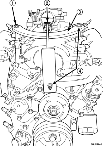
- Holding the lifting fixture at a slight angle, slide the large bore in the front plate over the hex portion of the lifting stud.
- Position the two remaining fixture arms onto the two Special Tools 8400 Lifting Studs, in the cylinder heads.
- Pull foward and upward on the lifting fixture so that the lifting stud rest in the slotted area below the large bore.
- Secure the lifting fixture to the three studs using three 7/16 – 14 N/C locknuts.
- Make sure the lifting loop in the lifting fixture is in the last hole (closest to the throttle body) to minimize the angle of engine during removal.
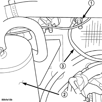
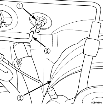
NOTE: It will be necessary to support the transmission in order to remove the engine.