U0019-CAN B BUS
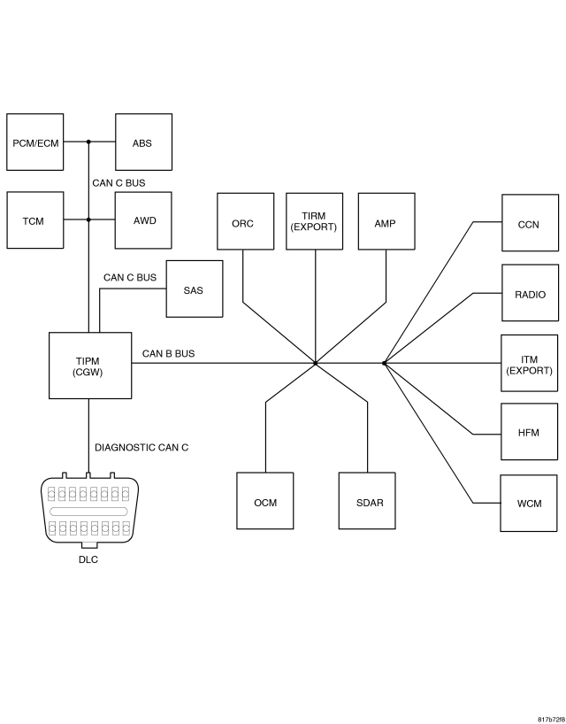
For a complete wiring diagram Refer to Section 8W.
- When Monitored:
With the ignition on.
- Set Condition:
The TIPM detects an open, a short high, a short low or a short together in either of the CAN B Bus circuits.
| Possible Causes |
| (D55) CAN B BUS (+) CIRCUIT OPEN |
| (D54) CAN B BUS (-) CIRCUIT OPEN |
| (D55) CAN B BUS (+) CIRCUIT SHORTED TO VOLTAGE |
| (D54) CAN B BUS (-) CIRCUIT SHORTED TO VOLTAGE |
| (D55) CAN B BUS (+) CIRCUIT SHORTED TO GROUND |
| (D54) CAN B BUS (-) CIRCUIT SHORTED TO GROUND |
| (D55) CAN B BUS (+) CIRCUIT SHORTED TO (D54) CAN B BUS (-) CIRCUIT |
| ANY CAN B BUS MODULE |
Diagnostic Test
1.TEST FOR INTERMITTENT CONDITIONNOTE: Check for any TSB(s) related to the condition. If a TSB applies, perform the procedure outlined in the TSB before continuing.
Does the scan tool display this DTC as active?
Yes
- Go To 2
No
- The conditions that caused this code to set are not present at this time. Using the wiring diagram/schematic as a guide, inspect the wiring and connectors.
2.MEASURE VOLTAGE AT TIPM
Does the voltage read approximately 4.65 - 4.98 volts on the (D54) CAN B Bus (-) and 0.39 - 0.46 volts on the (D55) CAN B (+) circuits?
Yes
- Go To 3
No - Voltage Between 0.3 - 0.7 Volts on Both Circuits
- Go To 9
No - Voltage Reads 0 Volts on Either Circuit
- Go To 7
No - Voltage Above 10 Volts on Either Circuit
- Go To 5
3. (D55) CAN B BUS (+) CIRCUIT OPEN
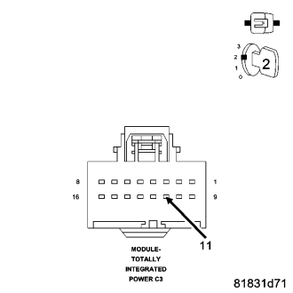
NOTE: A red “X” will appear next to modules that can no longer communicate on the Bus.
Did a red “X” appear next to any modules on the scan tool?
Yes
- Using the Wiring Diagrams to further isolate the open in the circuit, repair the (D55) CAN B Bus (+) circuit for an open.
- Perform the BODY VERIFICATION TEST – VER 1. (Refer to 8 - ELECTRICAL/ELECTRONIC CONTROL MODULES - STANDARD PROCEDURE).
No
- Go To 4
4. (D54) CAN B BUS (-) CIRCUIT OPEN
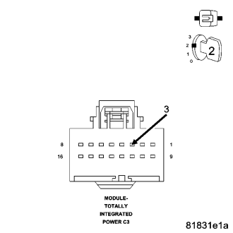
NOTE: A red “X” will appear next to modules that can no longer communicate on the Bus.
Did a red “X” appear next to any modules on the scan tool?
Yes
- Using the Wiring Diagrams to further isolate the open in the circuit, repair the (D54) CAN B Bus (-) circuit for an open.
- Perform the BODY VERIFICATION TEST – VER 1. (Refer to 8 - ELECTRICAL/ELECTRONIC CONTROL MODULES - STANDARD PROCEDURE).
No
- Inspect the wiring and connectors for damage. If ok, replace and program the Totally Integrated Power Module in accordance with the service information. Perform the BODY VERIFICATION TEST – VER 1. (Refer to 8 - ELECTRICAL/ELECTRONIC CONTROL MODULES - STANDARD PROCEDURE).
5.(D55) CAN B BUS (+) CIRCUIT FOR A SHORT TO VOLTAGE
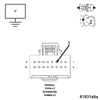
Is the voltage above 10.0 volts?
Yes
- Disconnect each CAN B Bus module one at a time while observing the voltage to determine if the short is caused by an internal short within a module. Replace the module, in accordance with the service information, that when disconnected eliminates the short to voltage. If the short condition is still present with all CAN B Bus modules disconnected use the Wiring Diagrams to help isolate and repair the (D55) CAN B Bus (+) circuit for a short to voltage.
- Perform the BODY VERIFICATION TEST – VER 1. (Refer to 8 - ELECTRICAL/ELECTRONIC CONTROL MODULES - STANDARD PROCEDURE).
No
- Go To 6
6.(D54) CAN B BUS (-) CIRCUIT FOR A SHORT TO VOLTAGE
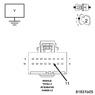
Is the voltage above 10.0 volts?
Yes
- Disconnect each CAN B Bus module one at a time while observing the voltage to determine if the short is caused by an internal short within a module. Replace the module, in accordance with the service information, that when disconnected eliminates the short to voltage. If the short condition is still present with all CAN B Bus modules disconnected use the Wiring Diagrams to help isolate and repair the (D54) CAN B Bus (-) circuit for a short to voltage.
- Perform the BODY VERIFICATION TEST – VER 1. (Refer to 8 - ELECTRICAL/ELECTRONIC CONTROL MODULES - STANDARD PROCEDURE).
No
- Inspect the wiring and connectors for damage. If ok, replace and program the Totally Integrated Power Module in accordance with the service information. Perform the BODY VERIFICATION TEST – VER 1. (Refer to 8 - ELECTRICAL/ELECTRONIC CONTROL MODULES - STANDARD PROCEDURE).
7.(D55) CAN B BUS (+) CIRCUIT FOR A SHORT TO GROUND
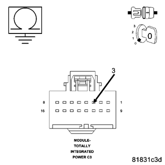
Is the resistance above 1000.0 ohms?
Yes
- Go To 8
No
- Disconnect each CAN B Bus module one at a time while observing the resistance to determine if the short is caused by an internal short within a module. Replace the module, in accordance with the service information, that when disconnected eliminates the short to ground. If the short condition is still present with all CAN B Bus modules disconnected use the Wiring Diagrams to help isolate and repair the (D55) CAN B Bus (+) circuit for a short to ground.
- Perform the BODY VERIFICATION TEST – VER 1. (Refer to 8 - ELECTRICAL/ELECTRONIC CONTROL MODULES - STANDARD PROCEDURE).
8.(D54) CAN B BUS (-) CIRCUIT FOR A SHORT TO GROUND
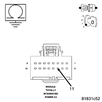
Is the resistance above 1000.0 ohms?
Yes
- Inspect the wiring and connectors for damage. If ok, replace and program the Totally Integrated Power Module in accordance with the service information. Perform the BODY VERIFICATION TEST – VER 1. (Refer to 8 - ELECTRICAL/ELECTRONIC CONTROL MODULES - STANDARD PROCEDURE).
No
- Disconnect each CAN B Bus module one at a time while observing the resistance to determine if the short is caused by an internal short within a module. Replace the module, in accordance with the service information, that when disconnected eliminates the short to ground. If the short condition is still present with all CAN B Bus modules disconnected use the Wiring Diagrams to help isolate and repair the (D54) CAN B Bus (-) circuit for a short to ground.
- Perform the BODY VERIFICATION TEST – VER 1. (Refer to 8 - ELECTRICAL/ELECTRONIC CONTROL MODULES - STANDARD PROCEDURE).
9. (D55) CAN B BUS (+) CIRCUIT SHORTED TO THE (D54) CAN B BUS (-) CIRCUIT
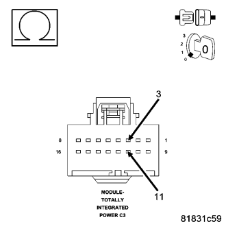
Is any resistance present?
Yes
- Disconnect each CAN B Bus module one at a time while observing the resistance to determine if the short is caused by an internal short within a module. Replace the module, in accordance with the service information, that when disconnected eliminates the short between the two circuits. If the short condition is still present with all CAN B Bus modules disconnected use the Wiring Diagrams to help isolate and repair the (D55) CAN B Bus (+) circuit for a short to the (D54) CAN B Bus (-) circuit.
- Perform the BODY VERIFICATION TEST – VER 1. (Refer to 8 - ELECTRICAL/ELECTRONIC CONTROL MODULES - STANDARD PROCEDURE).
No
- Inspect the wiring and connectors for damage. If ok, replace and program the Totally Integrated Power Module in accordance with the service information. Perform the BODY VERIFICATION TEST – VER 1. (Refer to 8 - ELECTRICAL/ELECTRONIC CONTROL MODULES - STANDARD PROCEDURE).