*CHECKING THE EVAPORATIVE SYSTEM FOR LEAKS
For a complete wiring diagram Refer to Section 8W.
Diagnostic Test
1.EVAPORATIVE SYSTEM INSPECTIONWere any problems found?
Yes
- Repair as necessary.
- Perform the PCM Verification Test. (Refer to 9 - ENGINE - STANDARD PROCEDURE)
No
- Go to 2
2.EVAPORATIVE SYSTEM LEAK
WARNING: Keep lit cigarettes, sparks, flames, and other ignition sources away from the test area to prevent the ignition of explosive gases. Keep the test area well ventilated. Failure to follow these instructions can result in personal injury or death.
NOTE: The fuel tank should have between 20% and 80% of fuel tank capacity to properly test the EVAP system.
NOTE: Vehicles with large volume fuel tanks, lower fuel levels, or vehicles equipped with a flow management valve may indicate high flow and will require 4 to 5 minutes to fill.
Is the indicator ball above the red flag?
Yes
- Go to 3
No
- Refer to the Freeze Frame data, if applicable. If the Freeze Frame data indicates that the vehicle was in motion when the DTC was set, verify that all hoses are connected properly.
- Perform the PCM Verification Test. (Refer to 9 - ENGINE - STANDARD PROCEDURE)
3.EVAPORATIVE EMISSION LEAK DETECTION
NOTE: A thorough inspection of the EVAP system hoses, tubes, and connections may save time in diagnosis. Look for physical damage or signs of wetness at connections. The strong smell of fuel vapors may aid diagnosis also.
NOTE: The flow meter indicator ball will not move in the smoke mode.
NOTE: Make sure that smoke has filled the EVAP system by continuing to press the remote smoke/air start button, remove the vehicle fuel cap, and wait for the smoke to exit. Once smoke is detected, reinstall the fuel cap.
NOTE: For the best results, introduce smoke into the system for an additional 60 seconds and continue introducing smoke at 15 second intervals, as necessary.
Were any problems found?
Yes
- Repair or replace the leaking component as necessary.
- Perform the PCM Verification Test. (Refer to 9 - ENGINE - STANDARD PROCEDURE)
No
- Go to 4
4.CHECKING THE GAS CAP AND FUEL FILLER TUBE
Was a leak found at the gas cap or filler tube?
Yes
- Go to 5
No
- Go to 6
5.GAS CAP OR FUEL FILLER TUBE
Was a leak found at the gas cap adapter?
Yes
- Replace the fuel filler tube assembly.
- Perform the PCM Verification Test. (Refer to 9 - ENGINE - STANDARD PROCEDURE)
No
- Replace the gas cap.
- Perform the PCM Verification Test. (Refer to 9 - ENGINE - STANDARD PROCEDURE)
6.CHECKING FOR EVAPORATIVE SYSTEM LEAKS IN ZONE 1
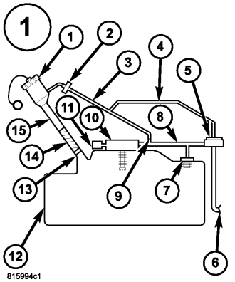
NOTE: For testing purposes, the EVAP System is divided into three zones. A leak from any of these zones can cause a DTC to set. The lists in the following steps below specify possible leak points in one of the specific zones.
Were any problems found?
Yes
- Repair or replace the leaking component as necessary.
- Perform the PCM Verification Test. (Refer to 9 - ENGINE - STANDARD PROCEDURE)
No
- Go to 7
7.CHECKING FOR EVAPORATIVE SYSTEM LEAKS IN ZONE 2
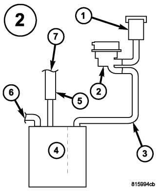
NOTE: For testing purposes, the EVAP System is divided into three zones. A leak from any of these zones can cause a DTC to set. The lists in the following steps below specify possible leak points in one of the specific zones.
Were any problems found?
Yes
- Repair or replace the leaking component as necessary.
- Perform the PCM Verification Test. (Refer to 9 - ENGINE - STANDARD PROCEDURE)
No
- Go to 8
8.CHECKING FOR EVAPORATIVE SYSTEM LEAKS IN ZONE 3
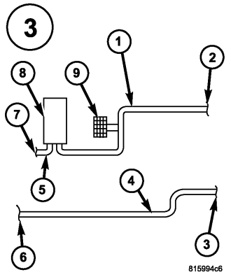
NOTE: For testing purposes, the EVAP System is divided into three zones. A leak from any of these zones can cause a DTC to set. The lists in the following steps below specify possible leak points in one of the specific zones.
Were any problems found?
Yes
- Repair or replace the leaking component as necessary.
- Perform the PCM Verification Test. (Refer to 9 - ENGINE - STANDARD PROCEDURE)
No
- Test complete.