*CHECKING THE ENGINE COOLANT TEMPERATURE SENSOR OPERATION
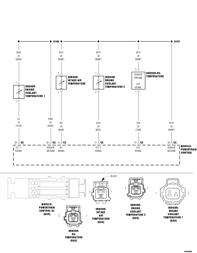
For a complete wiring diagram Refer to Section 8W.
Diagnostic Test
1.ENGINE COOLANT TEMPERATURE SENSOR WIRING OR CONNECTORSNOTE: Diagnose and repair any ECT circuit DTCs before proceeding with this test.
NOTE: Allow the engine to cool to ambient temperature before proceeding.
Were any problems found?
Yes
- Repair as necessary in accordance with the Service Information.
- Perform the PCM Verification Test. (Refer to 9 - ENGINE - STANDARD PROCEDURE)
No
- Go to 2
2.ENGINE COOLANT LEVEL AND CONDITION
WARNING: Make sure the engine cooling system is cool before removing the pressure cap or any hose. The cooling system is pressurized when hot. Failure to follow these instructions can result in personal injury including extreme burns, scalding, or death.
Were any problems found?
Yes
- Repair as necessary in accordance with the Service Information.
- Perform the PCM Verification Test. (Refer to 9 - ENGINE - STANDARD PROCEDURE)
No
- Go to 3
3.THERMOSTAT
WARNING: Make sure the engine cooling system is cool before removing the pressure cap or any hose. The cooling system is pressurized when hot. Failure to follow these instructions can result in personal injury including extreme burns, scalding, or death.
WARNING: When the engine is operating, do not stand in direct line with the fan. Do not put your hands near the pulleys, belts, or fan. Do not wear loose clothing. Failure to follow these instructions can result in personal injury or death.
NOTE: Each thermostat should open at the temperature specified in the Service Information.
Were any problems found?
Yes
- Repair as necessary in accordance with the Service Information.
- Perform the PCM Verification Test. (Refer to 9 - ENGINE - STANDARD PROCEDURE)
No
- Go to 4
4.ENGINE COOLANT TEMPERATURE SENSOR
NOTE: Allow the engine to cool to ambient temperature before proceeding.
WARNING: Make sure the engine cooling system is cool before removing the pressure cap or any hose. The cooling system is pressurized when hot. Failure to follow these instructions can result in personal injury including extreme burns, scalding, or death.
WARNING: When the engine is operating, do not stand in direct line with the fan. Do not put your hands near the pulleys, belts, or fan. Do not wear loose clothing. Failure to follow these instructions can result in personal injury or death.
NOTE: The sensor value transition should be smooth as the engine reaches operating temperature. The thermometer reading and the coolant temperature values on the scan tool should remain relatively close.
Were any problems found?
Yes
- Go to 5.
No
- Test complete.
5.ECT SIGNAL CIRCUIT HIGH RESISTANCE
NOTE: Perform this procedure for the sensor where erratic sensor values were detected in the previous test step.
CAUTION: Do not probe the PCM harness connectors. Probing the PCM harness connectors will damage the PCM terminals resulting in poor terminal to pin connection. Install Miller Special Tool #8815 along with the #8815-1 to perform the diagnosis.
WARNING: When the engine is operating, do not stand in direct line with the fan. Do not put your hands near the pulleys, belts, or fan. Do not wear loose clothing. Failure to follow these instructions can result in personal injury or death.
Is the voltage below 0.5 volts?
Yes
- Go to 6
No
- Repair the ECT Signal circuit for excessive resistance.
- Perform the PCM Verification Test. (Refer to 9 - ENGINE - STANDARD PROCEDURE)
6.SENSOR GROUND CIRCUIT HIGH RESISTANCE
CAUTION: Do not probe the PCM harness connectors. Probing the PCM harness connectors will damage the PCM terminals resulting in poor terminal to pin connection. Install Miller Special Tool #8815 along with the #8815-1 to perform the diagnosis.
WARNING: When the engine is operating, do not stand in direct line with the fan. Do not put your hands near the pulleys, belts, or fan. Do not wear loose clothing. Failure to follow these instructions can result in personal injury or death.
Is the voltage below 0.5 volts?
Yes
- Go to 7
No
- Repair the Sensor Ground circuit for excessive resistance.
- Perform the PCM Verification Test. (Refer to 9 - ENGINE - STANDARD PROCEDURE)
7.ENGINE COOLANT TEMPERATURE SENSOR
Were any problems found?
Yes
- Repair as necessary.
- Perform the PCM Verification Test. (Refer to 9 - ENGINE - STANDARD PROCEDURE)
No
- Replace the Engine Coolant Temperature Sensor.
- Perform the PCM Verification Test. (Refer to 9 - ENGINE - STANDARD PROCEDURE)