*CHECKING THE CHARGING SYSTEM OPERATION
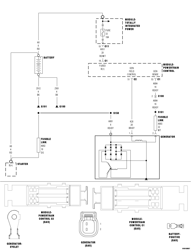
For a complete wiring diagram Refer to Section 8W.
Diagnostic Test
1.GENERATOR FULL FIELD TESTNOTE: Diagnose and repair any generator sense or field control circuit DTCs before proceeding with this test.
WARNING: When the engine is operating, do not stand in direct line with the fan. Do not put your hands near the pulleys, belts, or fan. Do not wear loose clothing. Failure to follow these instructions can result in personal injury or death.
NOTE: With the engine running, the difference between the system (battery) voltage and the generator sense voltage should be below .2 volts.
NOTE: With the generator field fully actuated, the system (battery) voltage should be above 14.0 volts.
NOTE: With the generator field actuated off, the system (battery) voltage should be below 13.0 volts, and eventually drop as battery load is increased.
Did the system voltage change as described above during the Generator Full Field test?
Yes
- Test complete.
No
- Go to 2
2.CHARGING SYSTEM INSPECTION
Were any problems found?
Yes
- Repair as necessary.
No
- Go to 3
3.BATTERY POSITIVE (+) CIRCUIT HIGH RESISTANCE
NOTE: Make sure all testing equipment and cables are clear of any engine parts before starting the engine.
WARNING: When the engine is operating, do not stand in direct line with the fan. Do not put your hands near the pulleys, belts, or fan. Do not wear loose clothing. Failure to follow these instructions can result in personal injury or death.
Is the voltage below 0.4 volts?
Yes
- Go to4
No
- Repair the battery positive (+) circuit between the generator and battery for high resistance.
- Perform the PCM Verification Test. (Refer to 9 - ENGINE - STANDARD PROCEDURE)
4.GENERATOR CASE GROUND HIGH RESISTANCE
NOTE: Make sure all testing equipment and cables are clear of any engine parts before starting the engine.
WARNING: When the engine is operating, do not stand in direct line with the fan. Do not put your hands near the pulleys, belts, or fan. Do not wear loose clothing. Failure to follow these instructions can result in personal injury or death.
Is the voltage below 0.1 volt?
Yes
- Go to5
No
- Repair the Generator Case ground for high resistance.
- Perform the PCM Verification Test. (Refer to 9 - ENGINE - STANDARD PROCEDURE)
5.(A109) FUSED B(+) CIRCUIT HIGH RESISTANCE
CAUTION: Do not probe the PCM harness connectors. Probing the PCM harness connectors will damage the PCM terminals resulting in poor terminal to pin connection. Install Miller Special Tool #8815 along with the #8815-1 to perform the diagnosis.
WARNING: When the engine is operating, do not stand in direct line with the fan. Do not put your hands near the pulleys, belts, or fan. Do not wear loose clothing. Failure to follow these instructions can result in personal injury or death.
Is the voltage below 0.5 volts?
Yes
- Go to 6
No
- Repair the (A109) Fused B(+) circuit(s) for high resistance.
- Perform the PCM Verification Test. (Refer to 9 - ENGINE - STANDARD PROCEDURE)
6.(A804) GENERATOR SENSE CIRCUIT HIGH RESISTANCE
CAUTION: Do not probe the PCM harness connectors. Probing the PCM harness connectors will damage the PCM terminals resulting in poor terminal to pin connection. Install Miller Special Tool #8815 along with the #8815-1 to perform the diagnosis.
WARNING: When the engine is operating, do not stand in direct line with the fan. Do not put your hands near the pulleys, belts, or fan. Do not wear loose clothing. Failure to follow these instructions can result in personal injury or death.
Is the voltage below 0.5 volts?
Yes
- Go to 7
No
- Repair the (A804) Generator Sense circuit for high resistance.
- Perform the PCM Verification Test. (Refer to 9 - ENGINE - STANDARD PROCEDURE)
7.(K20) GEN FIELD CONTROL CIRCUIT HIGH RESISTANCE
CAUTION: Do not probe the PCM harness connectors. Probing the PCM harness connectors will damage the PCM terminals resulting in poor terminal to pin connection. Install Miller Special Tool #8815 along with the #8815-1 to perform the diagnosis.
WARNING: When the engine is operating, do not stand in direct line with the fan. Do not put your hands near the pulleys, belts, or fan. Do not wear loose clothing. Failure to follow these instructions can result in personal injury or death.
Is the voltage below 0.5 volts?
Yes
- Go to 8
No
- Repair the (K20) Gen Field Control circuit for high resistance.
- Perform the PCM Verification Test. (Refer to 9 - ENGINE - STANDARD PROCEDURE)
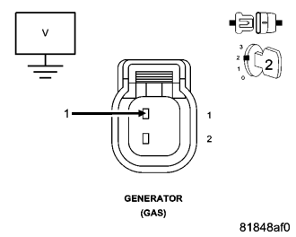
8.GENERATOR
NOTE: The test light should toggle on and off with the actuation.
NOTE: If a DTC is active, the actuation test may not be allowed by the PCM. If may be necessary to clear DTCs before starting the actuation.
Does the test light illuminate on and off with the actuation?
Yes
- Replace the Generator in accordance with the Service Information.
- Perform the PCM Verification Test. (Refer to 9 - ENGINE - STANDARD PROCEDURE)
No
- Go to9
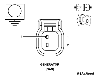
9.(K20) GEN FIELD CONTROL CIRCUIT SHORTED TO VOLTAGE
Is there any voltage present?
Yes
- Repair the (K20) Gen Field Control circuit for a short to voltage.
- Perform the PCM Verification Test. (Refer to 9 - ENGINE - STANDARD PROCEDURE)
No
- Go to 10
10.(K20) GEN FIELD CONTROL CIRCUIT SHORTED TO GROUND
Is the resistance below 100 ohms?
Yes
- Repair the (K20) Gen Field Control circuit for a short to ground.
- Perform the PCM Verification Test. (Refer to 9 - ENGINE - STANDARD PROCEDURE)
No
- Go to11
11.(K20) GEN FIELD CONTROL CIRCUIT OPEN OR HIGH RESISTANCE
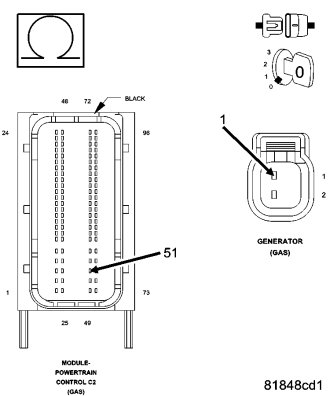
CAUTION: Do not probe the PCM harness connectors. Probing the PCM harness connectors will damage the PCM terminals, resulting in poor terminal to pin connection. Install Miller Special Tool #8815 to perform diagnosis.
Is the resistance below 5.0 ohms?
Yes
- Go to12
No
- Repair the (K20) Gen Field Control circuit for an open circuit or high resistance.
- Perform the PCM Verification Test. (Refer to 9 - ENGINE - STANDARD PROCEDURE)
12.CHECKING THE PCM POWER AND GROUND CIRCUITS
Were any problems found?
Yes
- Repair the PCM power and ground circuit(s) as necessary.
- Perform the PCM Verification Test. (Refer to 9 - ENGINE - STANDARD PROCEDURE)
No
- Go to 13
13.POWERTRAIN CONTROL MODULE (PCM)
Were any problems found?
Yes
- Repair as necessary.
- Perform the PCM Verification Test. (Refer to 9 - ENGINE - STANDARD PROCEDURE)
No
- Replace and program the Powertrain Control Module (PCM) in accordance with the Service Information.
- Perform the PCM Verification Test. (Refer to 9 - ENGINE - STANDARD PROCEDURE)