P2112-ELECTRONIC THROTTLE CONTROL - UNABLE TO OPEN
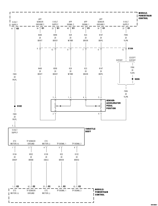
For a complete wiring diagram Refer to Section 8W.
- When Monitored:
Ignition on and battery voltage greater than 10 volts.
- Set Condition:
Just after key on, the throttle is opened and closed to test the system. If the PCM detects that the TP Sensor does not move from Limp Home Position, this DTC will set. One trip fault. The DTC will set within 5 seconds. ETC light is flashing.
| Possible Causes |
| INTERMITTENT DTC |
| THROTTLE PLATE STICKING OR OBSTRUCTED |
| TP SENSOR CIRCUIT(S) HIGH RESISTANCE OR SHORTED |
| (K124) ETC MOTOR (+) CIRCUIT SHORTED TO VOLTAGE |
| (K126) ETC MOTOR (-) CIRCUIT SHORTED TO VOLTAGE |
| (K124) ETC MOTOR (+) CIRCUIT SHORTED TO THE (K126) ETC MOTOR (-) CIRCUIT |
| (K124) ETC MOTOR (+) CIRCUIT OPEN OR HIGH RESISTANCE |
| (K126) ETC MOTOR (-) CIRCUIT OPEN OR HIGH RESISTANCE |
| (K124) ETC MOTOR (+) CIRCUIT SHORTED TO GROUND |
| (K126) ETC MOTOR (-) CIRCUIT SHORTED TO GROUND |
| THROTTLE BODY ASSEMBLY |
| PCM |
Always perform the Pre-Diagnostic Troubleshooting procedure before proceeding. (Refer to 9 - ENGINE - STANDARD PROCEDURE).
Diagnostic Test
1.ACTIVE DTCNOTE: Diagnose any TP Sensor or 5 Volt Supply DTCs before continuing.
WARNING: When the engine is operating, do not stand in direct line with the fan. Do not put your hands near the pulleys, belts, or fan. Do not wear loose clothing. Failure to follow these instructions can result in personal injury or death.
Is the status Active for this DTC?
Yes
- Go to 2
No
- Refer to the *CHECKING FOR AN INTERMITTENT DTC Diagnostic Procedure. (Refer to 9 - ENGINE - DIAGNOSIS AND TESTING)
2.THROTTLE PLATE INSPECTION
Were any problems found?
Yes
- Repair as necessary or replace the Throttle Body Assembly. Disconnect the battery when replacing the Throttle Body Assembly. After installation is complete, use a scan tool and select the ETC Relearn function.
- Perform the PCM Verification Test Ver. 1 (Refer to 9 - ENGINE - STANDARD PROCEDURE).
No
- Go to 3
3.TP SENSOR NO.1 AND TP SENSOR No. 2 BOTH EQUAL 2.5 VOLTS
Are both TP Sensor readings stuck at 2.5 volts?
Yes
- Check the TP Sensor Signal circuits for excessive resistance, being shorted together, or being shorted to the Sensor Ground circuit.
- Perform the PCM Verification Test Ver. 1 (Refer to 9 - ENGINE - STANDARD PROCEDURE).
No
- Go to 4
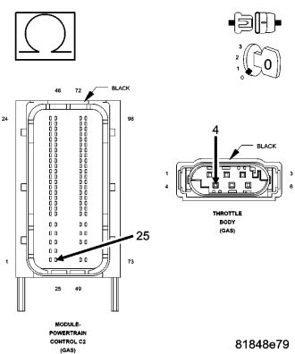
4.(K124) ETC MOTOR (+) CIRCUIT SHORTED TO VOLTAGE
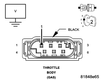
Is there any voltage present?
Yes
- Repair the (K124) ETC Motor (+) circuit for a short to voltage.
- Perform the PCM Verification Test Ver. 1 (Refer to 9 - ENGINE - STANDARD PROCEDURE).
No
- Go to 5
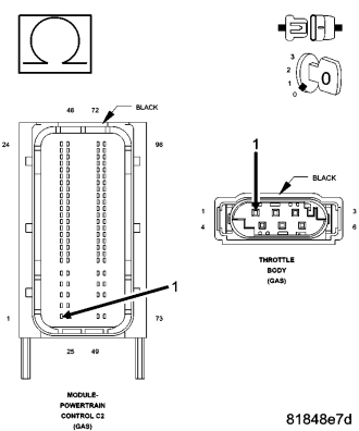
5.(K126) ETC MOTOR (-) CIRCUIT SHORTED TO VOLTAGE

Is there any voltage present?
Yes
- Repair the (K126) ETC Motor (-) circuit for a short to voltage.
- Perform the PCM Verification Test Ver. 1 (Refer to 9 - ENGINE - STANDARD PROCEDURE).
No
- Go to 6
6.(K124) ETC MOTOR (+) CIRCUIT SHORTED TO THE (K126) ETC MOTOR (-) CIRCUIT
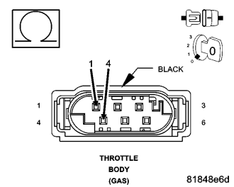
Is the resistance below 100 ohms?
Yes
- Repair the short to between the (K124) ETC Motor (+) circuit and the (K126) ETC Motor (-) circuit.
- Perform the PCM Verification Test Ver. 1 (Refer to 9 - ENGINE - STANDARD PROCEDURE).
No
- Go to 7
7.(K124) ETC MOTOR (+) CIRCUIT SHORTED TO GROUND
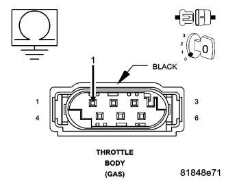
Is the resistance below 100 ohms?
Yes
- Repair the short to ground in the (K124) ETC Motor (+) circuit.
- Perform the PCM Verification Test Ver. 1 (Refer to 9 - ENGINE - STANDARD PROCEDURE).
No
- Go to 8
8.(K126) ETC MOTOR (-) CIRCUIT SHORTED TO GROUND

Is the resistance below 100 ohms?
Yes
- Repair the short to ground in the (K126) ETC Motor (-) circuit.
- Perform the PCM Verification Test Ver. 1 (Refer to 9 - ENGINE - STANDARD PROCEDURE).
No
- Go to 9
9.(K126) ETC MOTOR (-) CIRCUIT OPEN OR HIGH RESISTANCE
Is the resistance below 5.0 ohms?
Yes
- Go to 10
No
- Repair the (K126) ETC Motor (-) circuit for an open circuit or high resistance.
- Perform the PCM Verification Test Ver. 1 (Refer to 9 - ENGINE - STANDARD PROCEDURE).
10.(K124) ETC MOTOR (+) CIRCUIT OPEN OR HIGH RESISTANCE
Is the resistance below 5.0 ohms?
Yes
- Go to 11
No
- Repair the (K124) ETC Motor (+) circuit for an open circuit or high resistance.
- Perform the PCM Verification Test Ver. 1 (Refer to 9 - ENGINE - STANDARD PROCEDURE).
11.POWERTRAIN CONTROL MODULE (PCM)
Were any problems found?
Yes
- Repair as necessary.
- Perform the PCM Verification Test Ver. 1 (Refer to 9 - ENGINE - STANDARD PROCEDURE).
No
- Replace and program the Powertrain Control Module per Service Information.
- Perform the PCM Verification Test Ver. 1 (Refer to 9 - ENGINE - STANDARD PROCEDURE).