C123C–DYNAMICS SENSOR MOUNTING/INSTALLATION PERFORMANCE
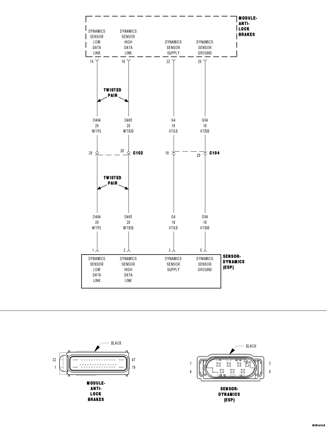
For a complete wiring diagram Refer to Section 8W.
- When Monitored:
With vehicle speed above 11 km/h (7 mph), but not if the sensor signal is invalid.
Or, during skidding.
Or, when driving in reverse.
- Set Condition:
If the Anti-Lock Brakes Module detects implausible Dynamics Sensor values.
| Possible Causes |
| WIRING HARNESS, TERMINAL, CONNECTOR DAMAGE |
| DYNAMICS SENSOR INSTALLATION |
| DYNAMICS SENSOR |
Diagnostic Test
1.VERIFY DTC IS ACTIVENOTE: If present, diagnose and repair DTC C2114–DYNAMICS SENSOR SUPPLY VOLTAGE LOW or DTC C2115–DYNAMICS SENSOR SUPPLY VOLTAGE HIGH before diagnosing this DTC.
WARNING: To avoid personal injury or death, check brake capability is available before road testing.
Does this DTC reset?
Yes
- Go To 2
No
- The condition that caused the symptom is currently not present. Inspect the related wiring for a possible intermittent condition. Look for any chafed, pierced, pinched, or partially broken wires.
- Refer to the ABS-INTERMITTENT CONDITION TEST. (Refer to 5 - BRAKES - DIAGNOSIS AND TESTING)
2.CHECK THE DYNAMICS SENSOR INSTALLATION
NOTE: Dynamics Sensor installation and mounting bolt torque is crucial for proper operation.
Were any problems found?
Yes
- Repair as necessary.
- Perform ABS VERIFICATION TEST. (Refer to 5 - BRAKES - STANDARD PROCEDURE).
No
- Go To 3
3.INSPECT RELATED WIRING HARNESS, TERMINALS, & CONNECTORS
Were any problems found?
Yes
- Repair as necessary.
- Perform ABS VERIFICATION TEST. (Refer to 5 - BRAKES - STANDARD PROCEDURE).
No
- Replace the Dynamics Sensor in accordance with the Service Information.
- Perform ABS VERIFICATION TEST. (Refer to 5 - BRAKES - STANDARD PROCEDURE).