TIRE AND WHEEL VIBRATION
Tire and wheel imbalance, runout and force variation can cause vehicles to exhibit steering wheel vibration.
VISUAL INSPECTION
Visual inspection of the vehicle is recommended prior to road testing or performing any other procedure. Raise the vehicle on a suitable hoist. (Refer to LUBRICATION & MAINTENANCE/HOISTING - STANDARD PROCEDURE)
Inspect for the following:
- Verify correct (OEM) wheel and tire, as well as correct wheel weights.
- Inspect tires and wheels for damage, mud packing and unusual wear; correct as necessary.
- Check and adjust tire air pressure to the pressure listed on the label attached to the driver's door opening.
ROAD TEST
Road test vehicle on a smooth road for a least five miles to warm tires (remove any flat spots). Lightly place hands on steering wheel at the 10:00 and 2:00 positions while slowly sweeping up and down from 90 to 110 km/h (55 to 70 mph) where legal speed limits allow.
Observe the steering wheel for:
- Visual Nibble (oscillation: clockwise/counterclockwise, usually due to tire imbalance)
- Visual Buzziness (high frequency, rapid vibration up and down)
To rule out vibrations due to brakes or powertrain:
- Lightly apply brakes at speed; if vibration occurs or is enhanced, vibration is likely due to causes other than tire and wheel assemblies.
- Shift transmission into neutral while vibration is occurring; if vibration is eliminated, vibration is likely due to causes other than tire and wheel assemblies.
For brake vibrations, (Refer to 5 - BRAKES - BASE/HYDRAULIC/MECHANICAL/ROTOR - DIAGNOSIS AND TESTING).
For powertrain vibrations, (Refer to 3 - DIFFERENTIAL & DRIVELINE).
For tire and wheel assembly vibrations, continue with this diagnosis and testing procedure.
TIRE AND WHEEL BALANCE
(Refer to 22 - TIRES/WHEELS - STANDARD PROCEDURE)
TIRE AND WHEEL RUNOUT/MATCH MOUNTING
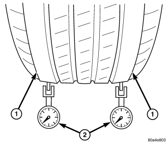
System Radial Runout.
(Refer to LUBRICATION & MAINTENANCE/HOISTING - STANDARD PROCEDURE)
- Tread "dips"; Rapid decrease then increase in dial indicator reading over 101.6 mm (4.0 inch) of tread circumference.
- Tread "steps"; Rapid decrease or increase in dial indicator reading over 101.6 mm (4.0 inch) of tread circumference.
(Refer to 5 - BRAKES - BASE/HYDRAULIC/MECHANICAL/ROTORS - DIAGNOSIS AND TESTING)
Tire and Wheel Assembly Radial Runout.
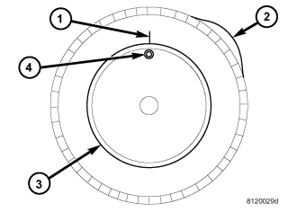
Lateral Runout.
Wheel Runout.
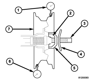
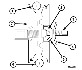
| WHEEL TYPE | RADIAL RUNOUT | LATERAL RUNOUT |
| Aluminum Wheel | 0.50 mm (0.020 inch) | 0.50 mm (0.020 inch) |
| Steel Wheel | 0.62 mm (0.024 inch) | 0.80 mm (0.031 inch) |
Match Mounting.
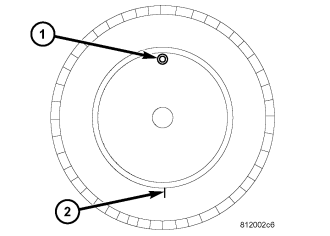
If runout is still excessive, perform the following:
- If the new high spot is within 102 mm (4.0 inch) of the first high spot on the tire, replace the tire.
- If the new high spot is within 102 mm (4.0 inch) of the first high spot on the wheel, the wheel may be out of specification. Refer to Wheel Runout above.
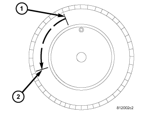
If the new high spot is NOT within 102 mm (4.0 inch) of either high spot, draw an arrow on the tread from new high spot toward the original (2). Break down the tire and remount it 90 degrees on rim in that direction, then re-measure runout. This will normally reduce the runout to an acceptable amount.