P0707-TRANSMISSION RANGE SENSOR CIRCUIT LOW
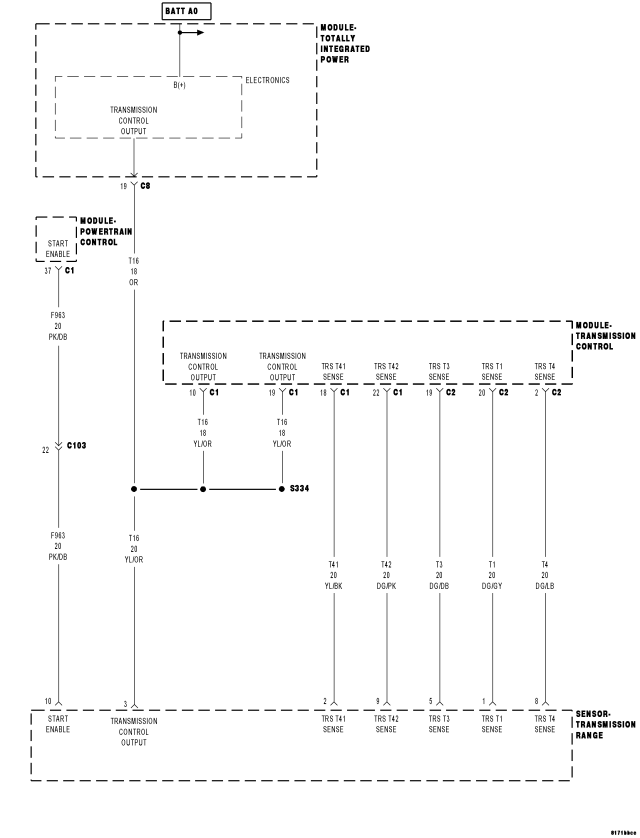
For a complete wiring diagram Refer to Section 8W.
Theory of Operation
The Transmission Range Sensor (TRS) has a contact point for each shift lever position. The Transmission Control Module (TCM) monitors the signal from the TRS which specifies the shift lever position. The TCM also broadcast the shift lever position over the CAN BUS to other modules.
- When Monitored:
Ignition on with system voltage between 9.0 and 16.0 volts.
Vehicle speed above 10 Km/h (6 mph).
No other Transmission Range Sensor (TRS) DTCs present.
- Set Condition:
If a continuous input signal loss is read by the TCM from the TRS for the period of 5 seconds. It takes two consecutive one trips of problem identification to light the MIL.
| Possible Causes |
| TRANSMISSION RANGE SENSOR CONNECTOR UNPLUGGED OR DAMAGED |
| TRANSMISSION RANGE SENSOR IMPROPERLY INSTALLED OR OUT OF ADJUSTMENT |
| (T16) TRANSMISSION CONTROL OUTPUT CIRCUIT OPEN |
| TRS SENSE CIRCUIT OPEN |
| TRS SENSE CIRCUIT SHORT TO GROUND |
| TRANSMISSION RANGE SENSOR |
| TRANSMISSION CONTROL MODULE |
Always perform the CVT Pre-Diagnostic Troubleshooting procedure before proceeding. (Refer to 21 - TRANSMISSION/TRANSAXLE/AUTOMATIC - CVT - STANDARD PROCEDURE)
Diagnostic Test
1.CHECK TO SEE IF THE DTC IS ACTIVEIs the status Active or is the STARTS SINCE SET counter 2 or less for this DTC?
Yes
- Go To 2
No
- Go To 9
2.CHECK THE TRS HARNESS CONNECTOR
NOTE: If the Transmission Range Sensor is unplugged the vehicle will not start.
Were there any problems found?
Yes
- Repair as necessary.
- Perform CVT VERIFICATION TEST. (Refer to 21 - TRANSMISSION/TRANSAXLE/AUTOMATIC - CVT - STANDARD PROCEDURE)
No
- Go To 3
3.CHECK THE TRS INSTALLATION AND ADJUSTMENT
(Refer to 21 - TRANSMISSION/TRANSAXLE/AUTOMATIC - CVT/TRANSMISSION RANGE SENSOR - INSTALLATION)
Was the TRS properly installed and adjusted?
Yes
- Go To 4
No
- Properly install or adjust the TRS per the Service Information.
- Perform CVT VERIFICATION TEST. (Refer to 21 - TRANSMISSION/TRANSAXLE/AUTOMATIC - CVT - STANDARD PROCEDURE)
4.CHECK THE TRS READINGS ON THE SCAN TOOL
| SHIFT LEVER POSITION TO TRS SWITCH STATE | ||||
| PARK | REVERSE | NEUTRAL | DRIVE | LOW |
| T41 CLOSED | T42 CLOSED | T4 CLOSED | T3 CLOSED | T1 CLOSED |
NOTE: Vehicles equipped with the AutoStick feature will not have a low range shift position.
Pick which answer best describes your findings:
One TRS Sense circuit failed to change on the scan tool
- Go To 6
None of the TRS Sense circuits changed at all
- Go To 5
All TRS Sense circuits changed properly on the scan tool
- Check the Sift Lever Cable for proper adjustment and binding per the Service Information. If no problems are found, using the schematics as a guide, check the Transmission Control Module (TCM) terminals for corrosion, damage, or terminal push out. Pay particular attention to all power and ground circuits. Check for any Service Bulletins for possible causes that may apply. If again no problems are found, replace the TCM per the Service Information
- Perform CVT VERIFICATION TEST. (Refer to 21 - TRANSMISSION/TRANSAXLE/AUTOMATIC - CVT - STANDARD PROCEDURE)
5.CHECK THE (T16) TRANSMISSION CONTROL OUTPUT CIRCUIT FOR AN OPEN
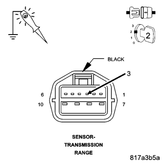
NOTE: The test light must illuminate brightly. Compare the brightness to that of a direct connection to the battery.
Does the test light illuminate brightly?
Yes
- Go To 8
No
- Repair the (T16) Transmission Control Output circuit for an open.
- Perform CVT VERIFICATION TEST. (Refer to 21 - TRANSMISSION/TRANSAXLE/AUTOMATIC - CVT - STANDARD PROCEDURE)
6.CHECK THE TRS SENSE CIRCUIT FOR AN OPEN
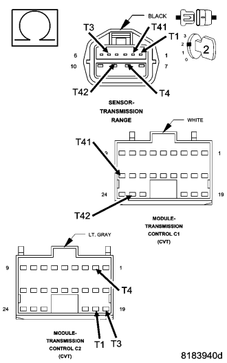
Is the resistance above 5.0 ohms?
Yes
- Repair the identified TRS Sense circuit for an open
- Perform CVT VERIFICATION TEST. (Refer to 21 - TRANSMISSION/TRANSAXLE/AUTOMATIC - CVT - STANDARD PROCEDURE)
No
- Go To 7
7.CHECK THE TRS SENSE CIRCUIT FOR A SHORT TO GROUND
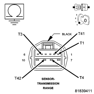
Is the resistance below 5.0 ohms?
Yes
- Repair the identified TRS Sense circuit for a short to ground
- Perform CVT VERIFICATION TEST. (Refer to 21 - TRANSMISSION/TRANSAXLE/AUTOMATIC - CVT - STANDARD PROCEDURE)
No
- Replace the Transmission Range Sensor (TRS) per the Service Information.
- Perform CVT VERIFICATION TEST. (Refer to 21 - TRANSMISSION/TRANSAXLE/AUTOMATIC - CVT - STANDARD PROCEDURE)
8.CHECK THE TRANSMISSION RANGE SENSOR
| SHIFT LEVER POSITION TO TRS SWITCH STATE | ||||
| PARK | REVERSE | NEUTRAL | DRIVE | LOW |
| T41 CLOSED | T42 CLOSED | T4 CLOSED | T3 CLOSED | T1 CLOSED |
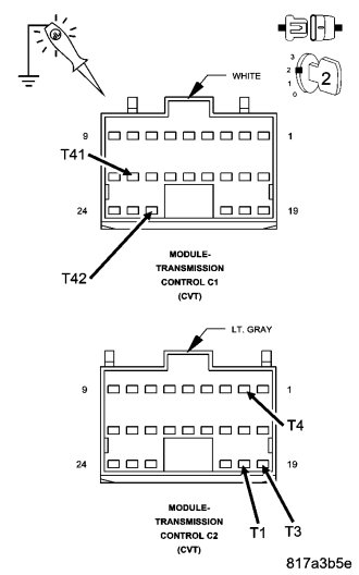
NOTE: Use the above chart to identify which sense circuit should be closed in each shift lever position.
Does the test light illuminate brightly on all the TRS Sense circuits?
Yes
- Using the schematics as a guide, check the Transmission Control Module (TCM) terminals for corrosion, damage, or terminal push out. Pay particular attention to all power and ground circuits. Check for any Service Bulletins for possible causes that may apply. If no problems are found, replace the TCM per the Service Information.
- Perform CVT VERIFICATION TEST. (Refer to 21 - TRANSMISSION/TRANSAXLE/AUTOMATIC - CVT - STANDARD PROCEDURE)
No
- Replace the Transmission Range Sensor per the Service Information.
- Perform CVT VERIFICATION TEST. (Refer to 21 - TRANSMISSION/TRANSAXLE/AUTOMATIC - CVT - STANDARD PROCEDURE)
9.INTERMITTENT WIRING AND CONNECTORS
Were there any problems found?
Yes
- Repair as necessary.
- Perform CVT VERIFICATION TEST. (Refer to 21 - TRANSMISSION/TRANSAXLE/AUTOMATIC - CVT - STANDARD PROCEDURE)
No
- Test Complete.