REMOVAL
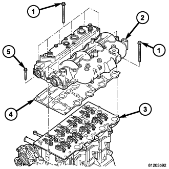
CAUTION: Before removing the cylinder head cover/intake manifold (2) the witness mark on the crankshaft hub must rotated to the 3 O'clock position or, 90° after TDC to assure proper alignment of the camshafts and the crankshaft. Failure to do so could result in valve and/or piston damage during reassembly.
(Refer to 9 - ENGINE - REMOVAL)
(Refer to 9 - ENGINE/AIR INTAKE SYSTEM/AIR CLEANER HOUSING - REMOVAL)
(Refer to 7 - COOLING/ENGINE/COOLANT - STANDARD PROCEDURE)
(Refer to 7 - COOLING/ENGINE/FAN DRIVE VISCOUS CLUTCH - REMOVAL)
(Refer to 7 - COOLING/ACCESSORY DRIVE/DRIVE BELTS - REMOVAL)
(Refer to 7 - COOLING/ENGINE/RADIATOR FAN - REMOVAL)
(Refer to 8 - ELECTRICAL/CHARGING/GENERATOR - REMOVAL)
L.H.Thread.
CAUTION: Before removing the cylinder head cover/intake manifold (2) the witness mark on the crankshaft hub must rotated to the 3 O'clock position or, 90° after TDC to assure proper alignment of the camshafts and the crankshaft. Failure to do so could result in valve and/or piston damage during reassembly.
NOTE: It may be necessary to rotate the camshaft gear bolt slightly to gain proper camshaft alignment pin seating against the intake manifold. Alignment pins must seat flush against the intake manifold.
(Refer to 9 - ENGINE/VALVE TIMING - STANDARD PROCEDURE)
(Refer to 9 - ENGINE/VALVE TIMING/TIMING BELT / CHAIN COVER(S) - REMOVAL)
(Refer to 9 - ENGINE/VALVE TIMING/TIMING BELT/CHAIN AND SPROCKETS - REMOVAL)
L.H.Thread.
(Refer to 9 - ENGINE/VALVE TIMING/TIMING BELT / CHAIN COVER(S) - REMOVAL)
(Refer to 14 - FUEL SYSTEM/FUEL INJECTION/FUEL INJECTOR - REMOVAL)
(Refer to 14 - FUEL SYSTEM/FUEL DELIVERY/FUEL RAIL - REMOVAL)
NOTE: When removing rocker arm and lifter assemblies, Always keep lifters in an upright position and in the order that they were removed from the cylinder head (3).