*NO CRANK CONDITION
For a complete wiring diagram Refer to Section 8W.
| Possible Causes |
| MECHANICAL CONDITION |
| BATTERY CIRCUIT RESISTANCE TOO HIGH |
| FUSED IGNITION SWITCH OUTPUT CIRCUITS |
| FUSED B+ CIRCUIT OPEN |
| (T752) STARTER RELAY CONTROL CIRCUIT OPEN |
| (T750) STARTER RELAY OUTPUT CIRCUIT OPEN |
| TRANSMISSION RANGE SENSOR |
| STARTER RELAY |
| STARTER |
Diagnostic Test
1.MECHANICAL CONDITIONNOTE: Verify the battery is fully charged and capable of passing a load test before continuing.
WARNING: Make sure the battery is disconnected, then wait two minutes before proceeding. Failure to do so may result in personal injury or possible death.
Is the engine able to turn over?
Yes
- Go To 2
No
- Repair the mechanical condition preventing the starter motor from cranking.
- Perform the POWERTRAIN VERIFICATION TEST. (Refer to 9 - ENGINE - STANDARD PROCEDURE)
2.TRANSMISSION RANGE SENSOR
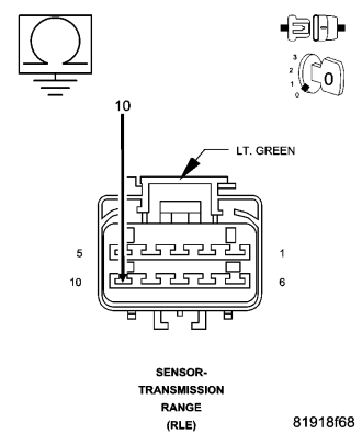
NOTE: The circuit is grounded in Park and Neutral and open in the other positions.
Did the resistance change from above 100 kohms (open) to below 10.0 ohms (grounded) ?
Yes
- Go To 3
No
- Replace the Transmission Range Sensor.
- Perform the POWERTRAIN VERIFICATION TEST. (Refer to 9 - ENGINE - STANDARD PROCEDURE)
3.EXCESSIVE RESISTANCE IN THE BATTERY CIRCUIT
Did either Battery Cable have a voltage drop greater than 0.2 of a volt?
Yes
- Repair the excessive resistance in the Battery circuit.
- Perform the POWERTRAIN VERIFICATION TEST. (Refer to 9 - ENGINE - STANDARD PROCEDURE)
No
- Go To 4
4.STARTER RELAY
Will the Starter Motor crank with the new relay?
Yes
- Replace the Starter Relay.
- Perform the POWERTRAIN VERIFICATION TEST. (Refer to 9 - ENGINE - STANDARD PROCEDURE)
No
- Go To 5
5.INTERNAL FUSED IGNITION SWITCH OUTPUT CIRCUIT
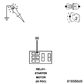
Does the test light illuminate brightly?
Yes
- Go To 6
No
- Repair the excessive resistance in the (F924) Fused Ignition Switch Output circuit. Inspect related fuses and repair as necessary.
- Perform the POWERTRAIN VERIFICATION TEST. (Refer to 9 - ENGINE - STANDARD PROCEDURE)
6.(T752) STARTER RELAY CONTROL CIRCUIT OPEN
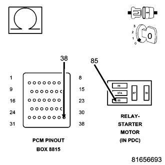
Is the resistance below 5.0 ohms?
Yes
- Go To 7
No
- Repair the open in the (T752) Starter Relay Control circuit.
- Perform the POWERTRAIN VERIFICATION TEST. (Refer to 9 - ENGINE - STANDARD PROCEDURE)
7.INTERNAL FUSED B+ CIRCUIT OPEN
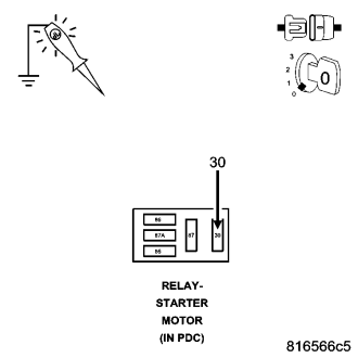
Does the test light illuminate brightly?
Yes
- Go To 8
No
- Repair the excessive resistance in the Internal Fused B+ circuit. Inspect related fuses and repair as necessary.
- Perform the POWERTRAIN VERIFICATION TEST. (Refer to 9 - ENGINE - STANDARD PROCEDURE)
8.(T750) STARTER RELAY OUTPUT CIRCUIT OPEN
Is the resistance below 5.0 ohms?
Yes
- Go To 9
No
- Repair the open in the (T750) Starter Relay Output circuit.
- Perform the POWERTRAIN VERIFICATION TEST. (Refer to 9 - ENGINE - STANDARD PROCEDURE)
9.STARTER
If there are no other possible causes remaining, review repair.
Repair
- Replace the Starter.
- Perform the POWERTRAIN VERIFICATION TEST. (Refer to 9 - ENGINE - STANDARD PROCEDURE)