P2100-ELECTRONIC THROTTLE CONTROL MOTOR CIRCUIT
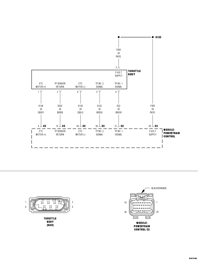
For a complete wiring diagram Refer to Section 8W.
- When Monitored:
With the ignition on and the ETC Motor is not in Limp Home mode.
- Set Condition:
When the PCM detects an internal error or a short between the ETC Motor- and ETC Motor + circuits in the ETC Motor Driver. One trip fault. ETC light is flashing.
| Possible Causes |
| THROTTLE PLATE / BORE INSPECTION |
| (K124) ETC POSITIVE CIRCUIT SHORTED TO BATTERY VOLTAGE |
| (K126) ETC NEGATIVE CIRCUIT SHORTED TO BATTERY VOLTAGE |
| (K124) ETC POSITIVE CIRCUIT SHORTED TO THE (K126) ETC NEGATIVE CIRCUIT |
| (K124) ETC POSITIVE CIRCUIT OPEN |
| (K124) ETC POSITIVE CIRCUIT SHORTED TO GROUND |
| (K126) ETC NEGATIVE CIRCUIT OPEN |
| (K126) ETC NEGATIVE CIRCUIT SHORTED TO GROUND |
| LOW BATTERY VOLTAGE |
| ETC MOTOR/THROTTLE BODY |
| PCM |
Always perform the Pre-Diagnostic Troubleshooting procedure before proceeding. (Refer to 9 - ENGINE - DIAGNOSIS AND TESTING).
Diagnostic Test
1.ACTIVE DTCNOTE: When this DTC is Active the engine speed, torque, and vehicle speed are limited to a Limp in mode.
NOTE: If the P2100 is intermittent, it is possible that the controller is overheating in extreme hot temperatures, and this is considered a normal protection operation. No repair is necessary.
NOTE: Low battery voltage can also cause excessive current draw, in very hot and very cold ambient temperatures. Make sure the battery can pass a load test before continuing.
Is the DTC Active at this time?
Yes
- Go To 2
No
- Refer to the INTERMITTENT CONDITION Diagnostic Procedure.
- Perform the POWERTRAIN VERIFICATION TEST. (Refer to 9 - ENGINE - STANDARD PROCEDURE)
2.THROTTLE PLATE INSPECTION
Were any signs of foreign material or scoring of the throttle plate or bore found?
Yes
- Remove the debris if possible or replace the Throttle Body Assembly. Disconnect the Battery when replacing the Throttle Body Assembly. After installation is complete, use a scan tool and select the ETC RELEARN function.
- Perform the POWERTRAIN VERIFICATION TEST. (Refer to 9 - ENGINE - STANDARD PROCEDURE)
No
- Go To 3
3.(K124) ETC POSITIVE CIRCUIT SHORTED TO BATTERY VOLTAGE
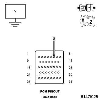
CAUTION: Do not probe the PCM harness connectors. Probing the PCM harness connectors will damage the PCM terminals resulting in poor terminal to pin connection. Install Miller Special Tool #8815 to perform the diagnostics.
Does the test light illuminate brightly?
Yes
- Repair the short to battery voltage on the (K124) ETC Positive circuit.
- Perform the POWERTRAIN VERIFICATION TEST. (Refer to 9 - ENGINE - STANDARD PROCEDURE)
No
- Go To 4
4.(K126) ETC NEGATIVE CIRCUIT SHORTED TO BATTERY VOLTAGE
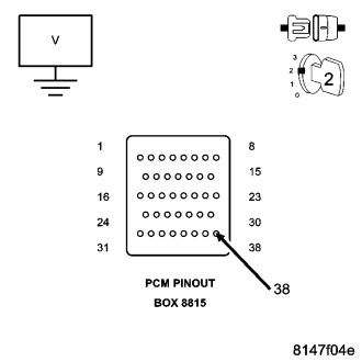
Does the test light illuminate brightly?
Yes
- Repair the short to battery voltage in the (K126) ETC Negative circuit.
- Perform the POWERTRAIN VERIFICATION TEST. (Refer to 9 - ENGINE - STANDARD PROCEDURE)
No
- Go To 5
5.(K124) ETC POSITIVE CIRCUIT SHORTED TO THE (K126) ETC NEGATIVE CIRCUIT
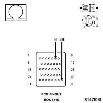
Is the resistance below 100 ohms?
Yes
- Repair the short to between the (K124) ETC Positive circuit and the (K126) ETC Negative circuit.
- Perform the POWERTRAIN VERIFICATION TEST. (Refer to 9 - ENGINE - STANDARD PROCEDURE)
No
- Go To 6
6.(K124) ETC POSITIVE CIRCUIT OPEN
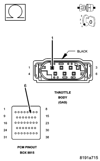
Is the resistance below 5.0 ohms?
Yes
- Go To 7
No
- Repair the open in the (K124) ETC Positive circuit.
- Perform the POWERTRAIN VERIFICATION TEST. (Refer to 9 - ENGINE - STANDARD PROCEDURE)
7.(K124) ETC POSITIVE CIRCUIT SHORTED TO GROUND
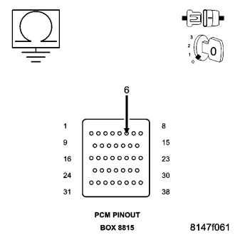
Is the resistance below 100 ohms?
Yes
- Repair the short to ground in the (K124) ETC Positive circuit.
- Perform the POWERTRAIN VERIFICATION TEST. (Refer to 9 - ENGINE - STANDARD PROCEDURE)
No
- Go To 8
8.(K126) ETC NEGATIVE CIRCUIT OPEN
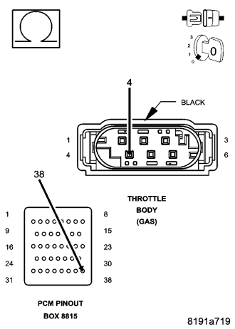
Is the resistance below 5.0 ohms?
Yes
- Go To 9
No
- Repair the open in the (K126) ETC Negative circuit.
- Perform the POWERTRAIN VERIFICATION TEST. (Refer to 9 - ENGINE - STANDARD PROCEDURE)
9.(K126) ETC NEGATIVE CIRCUIT SHORTED TO GROUND
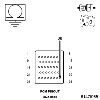
Is the resistance below 100 ohms?
Yes
- Repair the short to ground in the (K126) ETC Negative circuit.
- Perform the POWERTRAIN VERIFICATION TEST. (Refer to 9 - ENGINE - STANDARD PROCEDURE)
No
- Go To 10
10.ETC MOTOR
NOTE: Take the following measurement using special tool #8815 to avoid possible damage to the Throttle Body harness connector.
Is the resistance between 2.5 and 25 ohms at closed throttle?
Yes
- Go To 11
No
- Replace the Throttle Body Assembly. Disconnect the Battery when replacing the Throttle Body Assembly. After installation is complete, use a scan tool and select the ETC RELEARN function.
- Perform the POWERTRAIN VERIFICATION TEST. (Refer to 9 - ENGINE - STANDARD PROCEDURE)
11.PCM
NOTE: Before continuing, check the PCM harness connector terminals for corrosion, damage, or terminal push out. Repair as necessary.
Were there any problems found?
Yes
- Repair as necessary.
- Perform the POWERTRAIN VERIFICATION TEST. (Refer to 9 - ENGINE - STANDARD PROCEDURE)
No
- Replace and program the Powertrain Control Module per Service Information.
- Perform the POWERTRAIN VERIFICATION TEST. (Refer to 9 - ENGINE - STANDARD PROCEDURE)