P0627-FUEL PUMP CONTROL CIRCUIT

For a complete wiring diagram Refer to Section 8W.
- When Monitored:
With the ignition on. Battery voltage greater than 10.4 volts and the ASD sense switch is on.
- Set Condition:
Actual Fuel Pump Relay state is not equal to desired state. One Trip Fault. Three good trips to turn off the MIL.
| Possible Causes |
| (F1) FUSED IGNITION SWITCH OUTPUT CIRCUIT |
| INTERNAL FUSED B+ CIRCUIT |
| (K31) FUEL PUMP RELAY CONTROL CIRCUIT |
| (K31) FUEL PUMP RELAY CONTROL CIRCUIT SHORTED TO GROUND |
| FUEL PUMP RELAY |
| PCM |
Always perform the Pre-Diagnostic Troubleshooting procedure before proceeding. (Refer to 9 - ENGINE - DIAGNOSIS AND TESTING).
Diagnostic Test
1.FUEL PUMP RELAY OPERATIONIs the Fuel Pump Relay operating?
Yes
- Refer to the INTERMITTENT CONDITION Diagnostic Procedure.
- Perform the POWERTRAIN VERIFICATION TEST. (Refer to 9 - ENGINE - STANDARD PROCEDURE)
No
- Go To 2
2.FUEL PUMP RELAY
Is the resistance between 70 to 90 ohms?
Yes
- Go To 3
No
- Replace the Fuel Pump Relay.
- Perform the POWERTRAIN VERIFICATION TEST. (Refer to 9 - ENGINE - STANDARD PROCEDURE)
3. FUSED B+ CIRCUIT
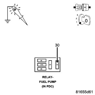
Does the test light illuminate brightly?
Yes
- Go To 4
No
- Repair the open or short to ground in the Fused B+ circuit. Inspect the related fuse and repair as necessary.
- Perform the POWERTRAIN VERIFICATION TEST. (Refer to 9 - ENGINE - STANDARD PROCEDURE)
4.(F1) FUSED IGNITION SWITCH OUTPUT CIRCUIT
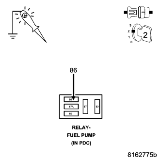
Does the test light illuminate brightly?
Yes
- Go To 5
No
- Repair the open or short to ground in the (F1) Fused Ignition Switch Output circuit. Inspect the related fuse and repair as necessary.
- Perform the POWERTRAIN VERIFICATION TEST. (Refer to 9 - ENGINE - STANDARD PROCEDURE)
5.(K31) FUEL PUMP CONTROL CIRCUIT OPEN
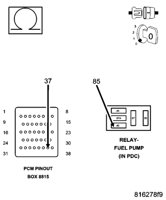
CAUTION: Do not probe the PCM harness connectors. Probing the PCM harness connectors will damage the PCM terminals resulting in poor terminal to pin connection. Install Miller Special Tool #8815 to perform diagnosis.
Is the resistance below 5.0 ohms?
Yes
- Go To 6
No
- Repair the open in the (K31) Fuel Pump Relay Control circuit.
- Perform the POWERTRAIN VERIFICATION TEST. (Refer to 9 - ENGINE - STANDARD PROCEDURE)
6.(K31) FUEL PUMP CONTROL CIRCUIT SHORTED TO GROUND
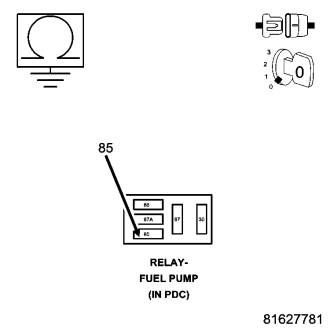
Is the resistance below 100 ohms?
Yes
- Repair the short to ground in the (K31) Fuel Pump Relay Control circuit.
- Perform the POWERTRAIN VERIFICATION TEST. (Refer to 9 - ENGINE - STANDARD PROCEDURE)
No
- Go To 7
7.PCM
NOTE: Before continuing, check the PCM harness connector terminals for corrosion, damage, or terminal push out. Repair as necessary.
Were there any problems found?
Yes
- Repair as necessary.
- Perform the POWERTRAIN VERIFICATION TEST. (Refer to 9 - ENGINE - STANDARD PROCEDURE)
No
- Replace and program the Powertrain Control Module per Service Information.
- Perform the POWERTRAIN VERIFICATION TEST. (Refer to 9 - ENGINE - STANDARD PROCEDURE)