P0339-CRANKSHAFT POSITION SENSOR CIRCUIT INTERMITTENT INCORRECT OR MISSING SIGNAL
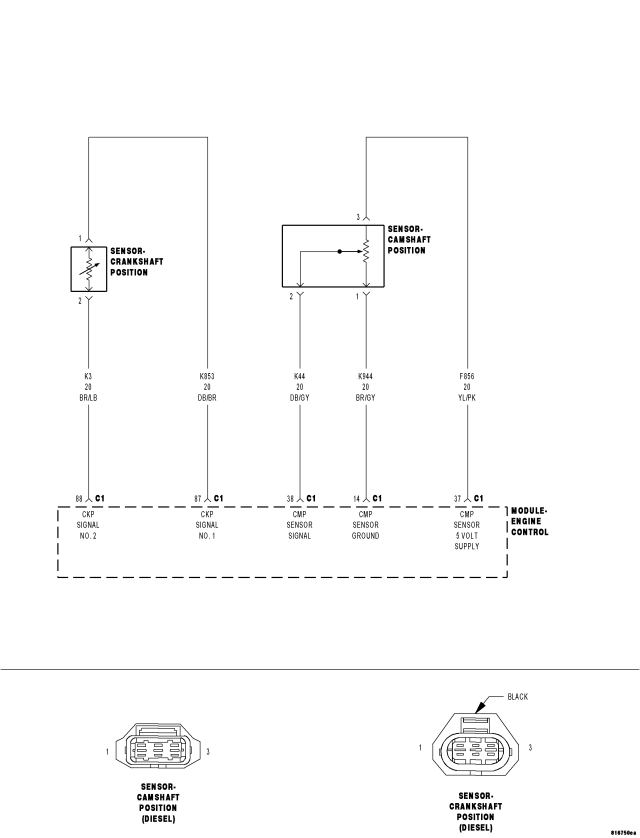
For a complete wiring diagram Refer to Section 8W
- When Monitored:
With the engine speed between 20 and 6000 rpm.
- Set Condition:
The ECM does not receive a Crankshaft Position Sensor signal or receives an incorrect signal.
| Possible Causes |
| CRANKSHAFT POSITION SENSOR |
| INTERMITTENT CONDITION |
| (K853, K3) CRANKSHAFT POSITION SENSOR SIGNAL CIRCUIT(S) SHORTED TO GROUND |
| (K853, K3) CKP SENSOR CIRCUITS SHORTED TOGETHER |
| (K853, K3) CKP SENSOR SIGNAL CIRCUITS OPEN |
| (K853, K3) CKP SENSOR SIGNAL CIRCUIT(S) SHORTED TO VOLTAGE |
| ENGINE CONTROL MODULE |
Diagnostic Test
1.ATTEMPT TO START THE ENGINENOTE: If the ECM detects and stores a DTC, the ECM also stores the engine/vehicle operating conditions under which the DTC was set. Some of these conditions are displayed on the scan tool at the same time the DTC is displayed.
NOTE: Before erasing stored DTCs, record these conditions. Attempting to duplicate these conditions may assist when checking for an active DTC.
Did the engine start?
Yes
- Refer to the *CHECKING FOR AN INTERMITTENT DTC Diagnostic Procedure. (Refer to 9 - ENGINE - DIAGNOSIS AND TESTING)
No
- Go To 2
2.(K853, K3) CKP SENSOR SIGNAL CIRCUITS SHORTED TO GROUND
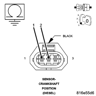
Is the resistance above 1000 ohms for both measurements?
Yes
- Go To 3
No
- Repair the CKP Sensor Signal circuit(s) for a short to ground.
- Perform the ECM Verification Test Ver. 1 (Refer to 9 - ENGINE - DIAGNOSIS AND TESTING).
3.(K853, K3) CKP SENSOR CIRCUITS SHORTED TOGETHER
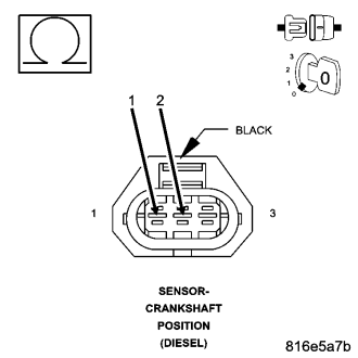
Is the resistance above 1000 ohms?
Yes
- Go To 4
No
- Repair the CKP Sensor Signal circuits for a short together.
- Perform the ECM Verification Test Ver. 1 (Refer to 9 - ENGINE - DIAGNOSIS AND TESTING).
4.(K853, K3) CKP SENSOR SIGNAL CIRCUIT(S) OPEN
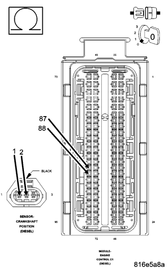
Is the resistance below 10.0 ohms for both measurements?
Yes
- Go To5
No
- Repair the CKP Sensor Signal circuit(s) for an open.
- Perform the ECM Verification Test Ver. 1 (Refer to 9 - ENGINE - DIAGNOSIS AND TESTING).
5.(K853, K3) CKP SENSOR SIGNAL CIRCUIT(S) SHORTED TO VOLTAGE
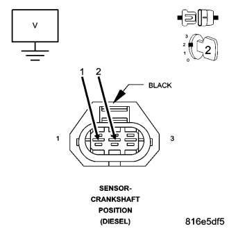
Is the voltage below 1.0 volt for both measurements?
Yes
- Go To 6
No
- Repair the CKP Sensor Signal circuit(s) for a short to voltage.
- Perform the ECM Verification Test Ver. 1 (Refer to 9 - ENGINE - DIAGNOSIS AND TESTING).
6.CRANKSHAFT POSITION SENSOR
Does the lab scope display a steady clean CKP Signal pattern for each circuit?
Yes
- Replace and program the Engine Control Module in accordance with the Service Information.
- Perform the ECM Verification Test Ver. 1 (Refer to 9 - ENGINE - DIAGNOSIS AND TESTING).
No
- Replace the Crankshaft Position Sensor.
- Perform the ECM Verification Test Ver. 1 (Refer to 9 - ENGINE - DIAGNOSIS AND TESTING).