B219A-IGNITION UNLOCK RUN/START CONTROL CIRCUIT OVERCURRENT
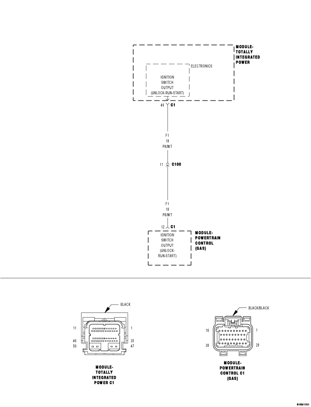
For a complete wiring diagram Refer to Section 8W.
- When Monitored:
With the ignition on.
- Set Condition:
Over current condition detected on the (F200) Fused Ignition Switch Output (Run-Start) circuit.
| Possible Causes |
| (F1) IGNITION SWITCH OUTPUT (UNLOCK-RUN-START) CIRCUIT SHORT TO GROUND |
| TERMINAL DAMAGE OR CORROSION |
| HIGH RESISTANCE ON THE (F1) FUSED IGNITION SWITCH OUTPUT (UNLOCK-RUN-START) CIRCUIT |
| POWERTRAIN CONTROL MODULE (PCM) |
| TIPM |
Diagnostic Test
1.CHECK FOR ACTIVE DTCDoes the scan tool display this DTC as active?
Yes
- Go To 2
No
- If the DTC is stored, check for an intermittent condition. Using the wiring diagram/schematic as a guide, visually inspect the related wiring harness connectors. Look for broken, bent, pushed out, or corroded terminals.
2.CHECK THE (F1) IGNITION SWITCH OUTPUT (UNLOCK-RUN-START) CIRCUIT FOR A SHORT TO GROUND
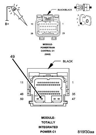
Does the test light illuminate brightly?
Yes
- Repair the (F1) Ignition Switch Output (Unlock-Run-Start) circuit for a short to ground.
- Perform BODY VERIFICATION TEST VER 1. (Refer to 8 - ELECTRICAL/ELECTRONIC CONTROL MODULES - STANDARD PROCEDURE)
No
- Go To 3
3.INSPECT THE TIPM & PCM TERMINALS & WIRE HARNESS FOR A CONDITION CAUSING HIGH CIRCUIT RESISTANCE
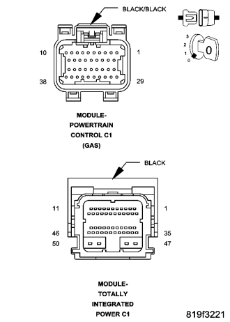
Were any of the above conditions found?
Yes
- Repair as necessary.
- Perform BODY VERIFICATION TEST VER 1. (Refer to 8 - ELECTRICAL/ELECTRONIC CONTROL MODULES - STANDARD PROCEDURE)
No
- Go To 4
4.
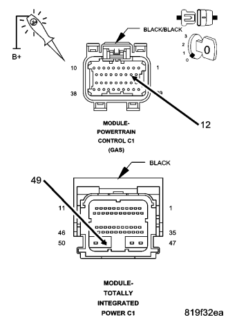
NOTE: The test light should be illuminated and bright. Compare the brightness to that of a direct connection to battery.
Does the test light illuminate brightly?
Yes
- Go To 5
No
- Repair the Fused Ignition Switch Output (Run-Start) Circuit for high resistance.
- Perform BODY VERIFICATION TEST VER 1. (Refer to 8 - ELECTRICAL/ELECTRONIC CONTROL MODULES - STANDARD PROCEDURE)
5.
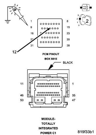
Does the test light illuminate brightly?
Yes
- Replace the PCM in accordance with the service information.
- Perform BODY VERIFICATION TEST VER 1. (Refer to 8 - ELECTRICAL/ELECTRONIC CONTROL MODULES - STANDARD PROCEDURE)
No
- Replace the TIPM in accordance with the service information.
- Perform BODY VERIFICATION TEST VER 1. (Refer to 8 - ELECTRICAL/ELECTRONIC CONTROL MODULES - STANDARD PROCEDURE)