*NO RESPONSE FROM TCM (POWERTRAIN CONTROL MODULE) - RFE
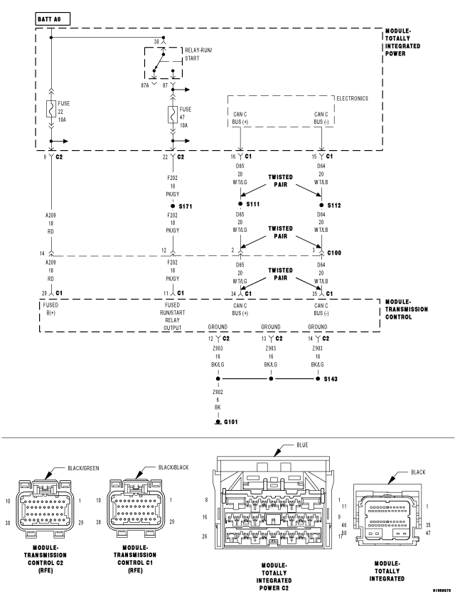
For a complete wiring diagram Refer to Section 8W.
| Possible Causes |
| (A209) FUSED B(+) CIRCUIT OPEN OR SHORTED |
| (Z903) GROUND CIRCUITS OPEN |
| (F202) FUSED RUN/START RELAY OUTPUT CIRCUIT OPEN OR SHORTED |
| (D65) CAN C BUS (+) CIRCUIT OPEN |
| (D64) CAN C BUS (-) CIRCUIT OPEN |
| POWERTRAIN CONTROL MODULE |
Diagnostic Test
1.TEST FOR INTERMITTENT CONDITIONNOTE: Ensure the IOD fuse is installed and battery voltage is between 10.0 and 16.0 volts.
NOTE: A red X will be next to the module that is not communicating, indicating that the module is not active on the Bus network. A green check indicates that the module is active on the Bus network.
NOTE: Check the TIPM for any active CAN C hardware DTCs, perform DTC before proceeding.
Does the scan tool display a red X next to the module?
Yes
- Go To 2
No
- The no response condition is not present at this time. Using the wiring diagram/schematic as a guide, inspect the wiring for chafed, pierced, pinched, and partially broken wires and the wiring harness connectors for broken, bent, pushed out, and corroded terminals.
2.ATTEMPT TO COMMUNICATE WITH THE PCM
Does the scan tool display a red X next to the PCM?
Yes
- Refer to the No Response From PCM test procedure. Refer to the table of contents in this section.
No
- Go To 3
3.(A209) FUSED B(+) CIRCUITS OPEN OR SHORTED
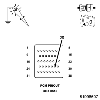
CAUTION: Do not probe the TCM harness connectors. Probing the TCM harness connectors will damage the TCM terminals resulting in poor terminal to pin connection. Install Miller Special Tool #8815 to perform diagnosis.
Does the test light illuminate brightly?
Yes
- Go To 4
No
- Repair the (A209) Fused B(+) circuit for an open or short.
- Perform the appropriate POWERTRAIN VERIFICATION TEST VER - 5.
4.(Z903) GROUND CIRCUITS OPEN
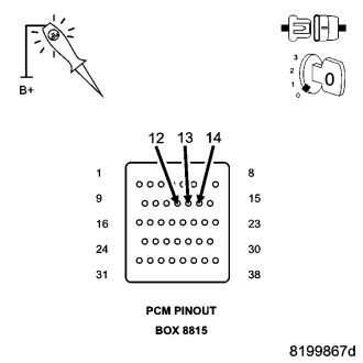
CAUTION: Do not probe the TCM harness connectors. Probing the TCM harness connectors will damage the TCM terminals resulting in poor terminal to pin connection. Install Miller Special Tool #8815 to perform diagnosis.
Does the test light illuminate brightly for each circuit?
Yes
- Go To 5
No
- Repair the ground circuit for an open.
- Perform the appropriate POWERTRAIN VERIFICATION TEST VER - 5.
5.(F202) FUSED RUN/START RELAY OUTPUT CIRCUIT OPEN OR SHORTED
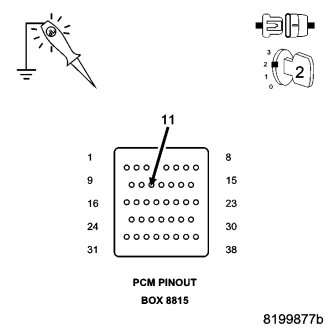
CAUTION: Do not probe the TCM harness connectors. Probing the TCM harness connectors will damage the TCM terminals resulting in poor terminal to pin connection. Install Miller Special Tool #8815 to perform diagnosis.
Does the test light illuminate brightly?
Yes
- Go To 6
No
- Repair the (F202) Fused Run/Start Relay Output circuit for an open or short.
- Perform the appropriate POWERTRAIN VERIFICATION TEST VER - 5.
6.(D65) CAN C BUS (+) CIRCUIT OPEN
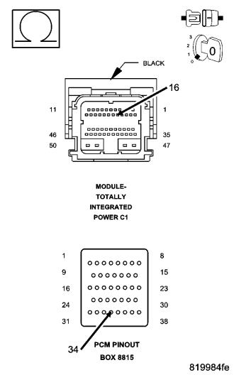
Is the resistance below 5.0 ohms?
Yes
- Go To 7
No
- Repair the (D65) CAN C Bus (+) circuit for an open.
- Perform the appropriate POWERTRAIN VERIFICATION TEST VER - 5.
7.(D64) CAN C BUS (-) CIRCUIT OPEN
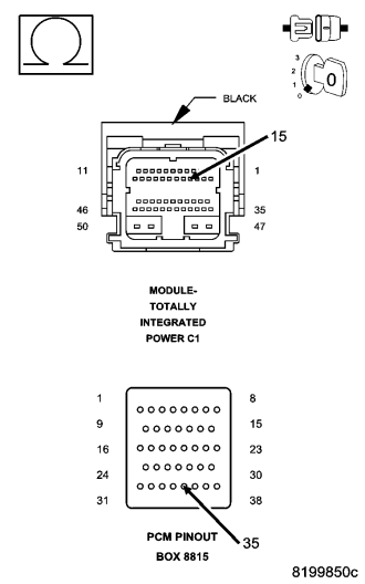
Is the resistance below 5.0 ohms?
Yes
- Replace and program the Transmission Control Module in accordance with the service information.
- Perform the appropriate POWERTRAIN VERIFICATION TEST VER - 5.
No
- Repair the (D64) CAN C Bus (-) circuit for an open.
- Perform the appropriate POWERTRAIN VERIFICATION TEST VER - 5.