U0141–LOST COMMUNICATION WITH FRONT CONTROL MODULE (TOTALLY INTEGRATED POWER MODULE)
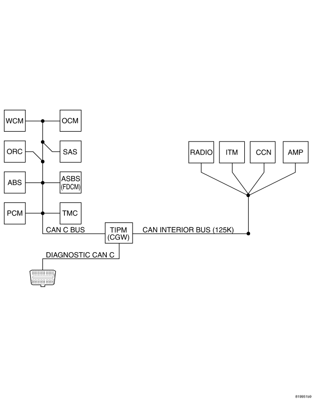
For a complete wiring diagram Refer to Section 8W.
- When Monitored:
With the ignition on.
Battery voltage between 10 and 16 volts.
IOD fuse installed.
TIPM is configured correctly.
- Set Condition:
Bus messages not received from the Totally Integrated Power Module (TIPM) for approximately 2 to 5 seconds.
| Possible Causes |
| DIAGNOSTIC CAN C BUS CIRCUITS OPEN OR SHORTED |
| DTCS RELATED TO BATTERY VOLTAGE, IGNITION, OR VIN MESSAGES |
| TIPM NOT CONFIGURED CORRECTLY |
| TOTALLY INTEGRATED POWER MODULE POWER AND GROUND |
| TOTALLY INTEGRATED POWER MODULE |
| MODULE THAT SET THIS DTC |
Diagnostic Test
1.VERIFY DTC IS ACTIVENOTE: Ensure the IOD fuse is installed and battery voltage is between 10 and 16 volts before proceeding.
Is this DTC active?
Yes
- Go To 2
No
- Refer to the Stored Lost Communication test procedure. Refer to the table of contents in this section.
2.CHECK FOR ANY OF THE FOLLOWING ACTIVE DTCS
NOTE: Check for TIPM configuration, CAN C hardware electrical, VIN Missing/Mismatch, battery or ignition related DTCs.
Does the scan tool display any active DTCs to the conditions listed above?
Yes
- Diagnose and repair the DTC. Refer to the Index for a complete list of the symptoms.
No
- Go To 3
3.VERIFY THAT THE TIPM IS ACTIVE ON THE BUS
Is the TIPM active on the bus?
Yes
- Go To 4
No
- Refer to the No Response test procedure. Refer to the table of contents in this section.
4.CHECK FOR ADDITIONAL COMMUNICATION RELATED DTCS
Is there more than one module with active DTCs “Logged Against” the TIPM?
Yes
- Replace/update the Totally Integrated Power Module (TIPM) in accordance with the service information.
- Perform the BODY VERIFICATION TEST – VER 1. (Refer to 8 - ELECTRICAL/ELECTRONIC CONTROL MODULES - STANDARD PROCEDURE).
No
- Replace/update the module that set this DTC in accordance with the service information
- Perform the appropriate VERIFICATION TEST.