C1405- TRANSFER CASE RANGE POSITION SENSOR CIRCUIT HIGH

For a complete wiring diagram Refer to Section 8W.
- When Monitored:
With the ignition on. Battery voltage between 9.0 and 16.0 volts
- Set Condition:
The TIPM detects 5.0 volts on the Transfer Case Range Position Sensor Signal circuit for 2.0 seconds when voltage should not be present.
| Possible Causes |
| (T313) MODE SENSOR SIGNAL CIRCUIT OPEN |
| (K91) SENSOR GROUND CIRCUIT OPEN |
| (T313) MODE SENSOR SIGNAL CIRCUIT SHORTED TO VOLTAGE |
| TRANSFER CASE (4WD) SWITCH |
| TOTALLY INTEGRATED POWER MODULE (TIPM) |
Diagnostic Test
1.T-CASE POSITION SENSOR VOLTAGE ABOVE 4.8 VOLTSIs the voltage above 4.8 volts?
Yes
- Go To 2
No
- Go To 7
2.(T313) MODE SENSOR SIGNAL CIRCUIT VOLTAGE

Is the voltage between 4.8 and 5.2 volts?
Yes
- Replace the Transfer Case (4WD) Switch in accordance with the Service Manual.
- Perform the TRANSFER CASE VERIFICATION TEST. (Refer to 21 - TRANSMISSION/TRANSAXLE/TRANSFER CASE - STANDARD PROCEDURE)
No
- Go To 3
3.(T313) MODE SENSOR SIGNAL CIRCUIT OPEN
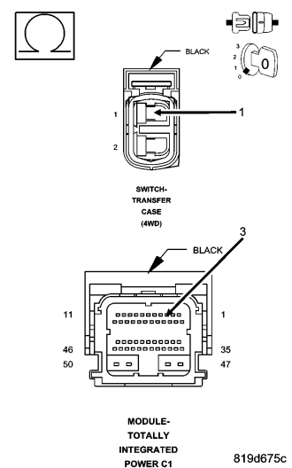
Is the resistance above 5.0 ohms?
Yes
- Repair the (T313) Mode Sensor Signal circuit for an open.
- Perform the TRANSFER CASE VERIFICATION TEST. (Refer to 21 - TRANSMISSION/TRANSAXLE/TRANSFER CASE - STANDARD PROCEDURE)
No
- Go To 4
4.(K91) SENSOR GROUND CIRCUIT OPEN
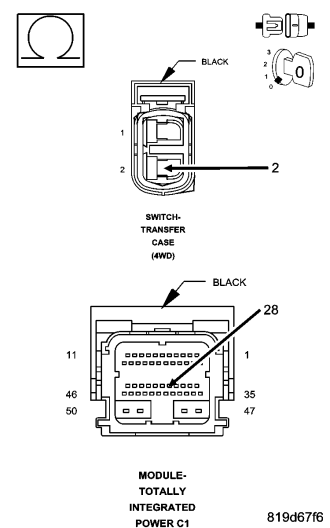
Is the resistance above 5.0 ohms?
Yes
- Repair the (K91) Sensor Ground circuit for an open.
- Perform the TRANSFER CASE VERIFICATION TEST. (Refer to 21 - TRANSMISSION/TRANSAXLE/TRANSFER CASE - STANDARD PROCEDURE)
No
- Go To 5
5.(T313) MODE SENSOR SIGNAL CIRCUIT SHORTED TO VOLTAGE
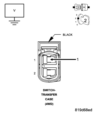
Is the voltage above 0.2 volts?
Yes
- Repair the (T313) Mode Sensor Signal circuit for a short to voltage.
- Perform the TRANSFER CASE VERIFICATION TEST. (Refer to 21 - TRANSMISSION/TRANSAXLE/TRANSFER CASE - STANDARD PROCEDURE)
No
- Go To 6
6.(K91) SENSOR GROUND CIRCUIT SHORTED TO VOLTAGE
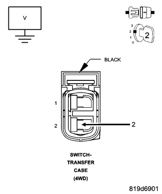
Is the voltage above 0.2 volts?
Yes
- Repair the (K91) Sensor Ground circuit for a short to voltage.
- Perform the TRANSFER CASE VERIFICATION TEST. (Refer to 21 - TRANSMISSION/TRANSAXLE/TRANSFER CASE - STANDARD PROCEDURE)
No
- Replace the Totally Integrated Power Module in accordance with the Service Information.
- Perform the TRANSFER CASE VERIFICATION TEST. (Refer to 21 - TRANSMISSION/TRANSAXLE/TRANSFER CASE - STANDARD PROCEDURE)
7.INTERMITTENT WIRING AND CONNECTORS
Were any problems found?
Yes
- Repair as necessary.
- Perform the TRANSFER CASE VERIFICATION TEST. (Refer to 21 - TRANSMISSION/TRANSAXLE/TRANSFER CASE - STANDARD PROCEDURE)
No
- Test complete.