P1115-GENERAL TEMPERATURE RATIONALITY
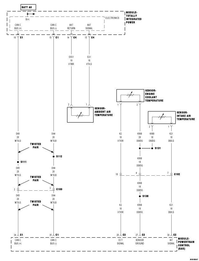
For a complete wiring diagram Refer to Section 8W.
Theory of Operation
The General Temperature Rationality looks at the outputs of the three temperature sensors and compare them under cold start conditions. Following a start to run delay time, the outputs of the ambient, engine coolant, and intake air temperature sensors will be compared. If two sensors agree but not the third, the third sensor is declared as irrational. If all three sensors are irrational the General Temperature Sensor Rationality is failed.
- When Monitored:
Ignition on and battery voltage greater than 10 volts.
- Set Condition:
Ambient Air, Engine Coolant, and Intake Air Temp sensor inputs are compared under cold start conditions. After start up the temp readings are monitored. If two of the three readings agree and the third doesn't, a DTC is stored. Two Trip Fault. Three good trips to turn off the MIL.
| Possible Causes |
| EXCESSIVE RESISTANCE IN THE SENSOR SIGNAL CIRCUIT |
| EXCESSIVE RESISTANCE IN THE SENSOR GROUND CIRCUIT |
| TEMPERATURE SENSOR |
| PCM |
Always perform the Pre-Diagnostic Troubleshooting procedure before proceeding. (Refer to 9 - ENGINE - DIAGNOSIS AND TESTING).
Diagnostic Test
1.ACTIVE DTCNOTE: All ECT, Intake Air, and Ambient Air Temperature Sensor codes must be diagnosed and repaired before continuing.
NOTE: In cold weather, this DTC could be set by a high powered block heater and no repair would be required.
NOTE: It may be necessary to test drive the vehicle to get the fault to an Active or Pending state because it takes two failed trips to set.
Is the DTC Active or Pending at this time?
Yes
- Go To 2
No
- Refer to the INTERMITTENT CONDITION Diagnostic Procedure.
- Perform the POWERTRAIN VERIFICATION TEST. (Refer to 9 - ENGINE - STANDARD PROCEDURE)
2.TEMPERATURE SENSOR CIRCUIT
Is the temperature for each of the Sensors increasing properly?
Yes
- Refer to the INTERMITTENT CONDITION Diagnostic Procedure.
- Perform the POWERTRAIN VERIFICATION TEST. (Refer to 9 - ENGINE - STANDARD PROCEDURE)
No
- Go To 3
3.TEMPERATURE SENSOR
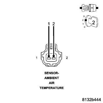
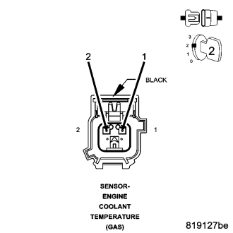
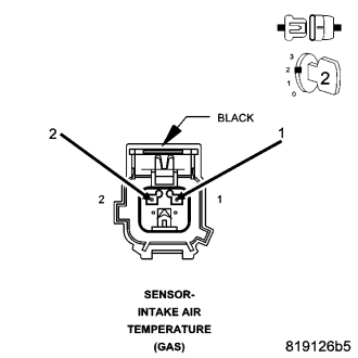
Did the voltage reading start at 4.8 to 5.0 volts and decrease to 0 volts when the jumper wire was installed?
Yes
- Replace the Sensor.
- Perform the POWERTRAIN VERIFICATION TEST. (Refer to 9 - ENGINE - STANDARD PROCEDURE)
No
- Go To 4
NOTE: Remove the jumper wire before continuing.
4.EXCESSIVE RESISTANCE IN THE TEMPERATURE SENSOR SIGNAL CIRCUIT
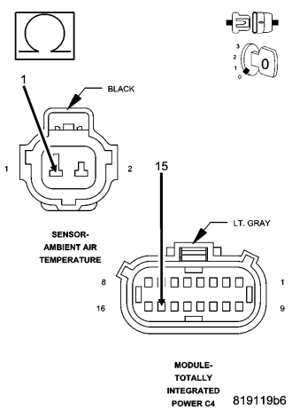
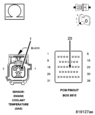
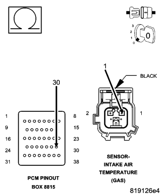
CAUTION: Do not probe the PCM harness connectors. Probing the PCM harness connectors will damage the PCM terminals resulting in poor terminal to pin connection. Install Miller Special Tool #8815 to perform diagnosis.
Is the resistance above 5.0 ohms.
Yes
- Repair the excessive resistance in the Temperature Sensor Signal circuit.
- Perform the POWERTRAIN VERIFICATION TEST. (Refer to 9 - ENGINE - STANDARD PROCEDURE)
No
- Go To 5
5.EXCESSIVE RESISTANCE IN THE SENSOR GROUND CIRCUIT
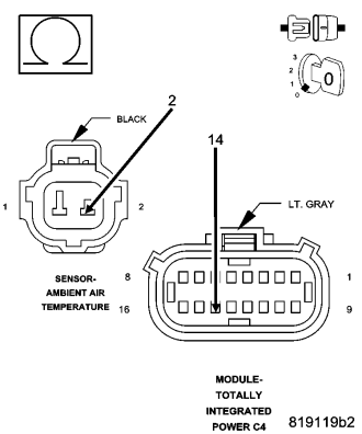
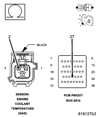
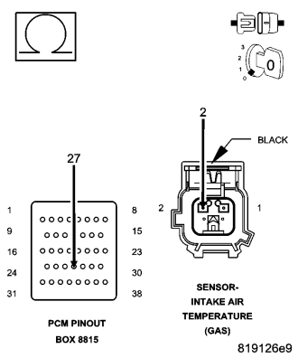
Is the resistance above 5.0 ohms.
Yes
- Repair the excessive resistance in the Sensor ground circuit.
- Perform the POWERTRAIN VERIFICATION TEST. (Refer to 9 - ENGINE - STANDARD PROCEDURE)
No
- Go To 6
6.PCM
NOTE: Before continuing, check the PCM harness connector terminals for corrosion, damage, or terminal push out. Repair as necessary.
Were there any problems found?
Yes
- Repair as necessary.
- Perform the POWERTRAIN VERIFICATION TEST. (Refer to 9 - ENGINE - STANDARD PROCEDURE)
No
- Replace and program the Powertrain Control Module per Service Information.
- Perform the POWERTRAIN VERIFICATION TEST. (Refer to 9 - ENGINE - STANDARD PROCEDURE)