P0401-EGR SYSTEM PERFORMANCE
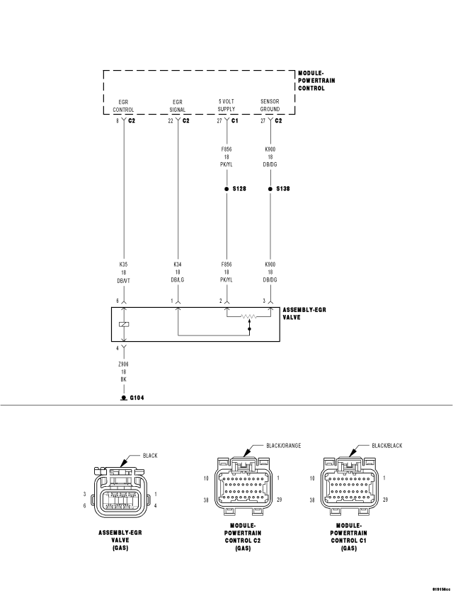
For a complete wiring diagram Refer to Section 8W.
Theory of Operation
Exhaust gas recirculation is a method of reducing emissions of oxides of nitrogen. As the inert exhaust gas is recirculated, the mixture absorbs heat in the combustion chamber without interacting with the fuel/air mixture and reduces the formation of NOx emissions. After the EGR monitor conditions are met, the EGR valve is turned on and off momentarily. The EGR monitor calculated the difference in engine roughness from the EGR off condition to the EGR condition. This engine combustion stability difference as measured by engine roughness is the measure of a functional EGR system.
- When Monitored:
Engine running for greater than two minutes with the Engine Coolant Temp greater than 70°C (158°F). EGR active. Less than 8500 feet. Ambient temperature greater than -6°C (20°F).
- Set Condition:
The PCM closes the EGR valve while monitoring the O2 Sensor signal. Once a closed EGR fueling sample has been established the PCM then ramps in EGR and additional fueling while monitoring the O2 sensor signal in the open state. A fueling sample is again established. The PCM then compares the different O2 Sensor signal readings (fueling samples). If a larger than expected variation is detected, a soft failure is recorded. Three soft failures set a one trip failure. After two failed trips, a DTC is set and the MIL is illuminated.
| Possible Causes |
| (Z906) EGR SOLENOID GROUND CIRCUIT OPEN |
| (K35) EGR SOLENOID CONTROL CIRCUIT SHORTED TO GROUND |
| (K35) EGR SOLENOID CONTROL CIRCUIT SHORTED TO BATTERY VOLTAGE |
| (K35) EGR SOLENOID CONTROL CIRCUIT OPEN |
| EGR SOLENOID ASSEMBLY |
| PCM |
Always perform the Pre-Diagnostic Troubleshooting procedure before proceeding. (Refer to 9 - ENGINE - DIAGNOSIS AND TESTING).
Diagnostic Test
1.ACTIVE DTCNOTE: It may be necessary to drive the vehicle to meet the conditions to set this DTC, try to repeat the conditions in which the fault originally set by reviewing the Freeze Frame data.
Is the DTC Active or Pending at this time?
Yes
- Go To 2
No
- Refer to the INTERMITTENT CONDITION Diagnostic Procedure.
- Perform the POWERTRAIN VERIFICATION TEST. (Refer to 9 - ENGINE - STANDARD PROCEDURE)
2.EGR OPERATION
NOTE: If the vehicle is running rough at idle (scan tool not actuating) follow the yes path to continue.
Did the engine run rough or stall?
Yes
- Go To 3
No
- Go To 6
3.EGR VALVE OPEN AT IDLE
Does the engine run rough or stall?
Yes
- Inspect the EGR tube assembly. If OK, replace the EGR valve.
- Perform the POWERTRAIN VERIFICATION TEST. (Refer to 9 - ENGINE - STANDARD PROCEDURE)
No
- Go To 4
4.EGR VALVE ASSEMBLY INSPECTION
Were any problem found?
Yes
- Repair or replace the EGR Assembly as necessary.
- Perform the POWERTRAIN VERIFICATION TEST. (Refer to 9 - ENGINE - STANDARD PROCEDURE)
No
- Go To 5
5.(K35) EGR SOLENOID CONTROL CIRCUIT SHORTED TO BATTERY VOLTAGE
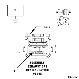
Is the voltage above 1.0 volt?
Yes
- Repair the short to battery voltage in the (K35) EGR Solenoid Control circuit.
- Perform the POWERTRAIN VERIFICATION TEST. (Refer to 9 - ENGINE - STANDARD PROCEDURE)
No
- Go To 10
6.EGR SOLENOID ASSEMBLY
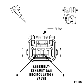
Does the 12-volt test light flash on and off?
Yes
- Inspect the tube(s) for obstructions and damage, repair as necessary. If OK, replace the EGR Solenoid Assembly.
- Perform the POWERTRAIN VERIFICATION TEST. (Refer to 9 - ENGINE - STANDARD PROCEDURE)
No
- Go To 7
7. (Z906) EGR SOLENOID GROUND CIRCUIT OPEN
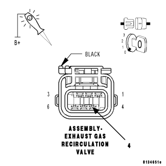
Does the 12-volt test light illuminate brightly?
Yes
- Go To 8
No
- Repair the open in the (Z906) EGR Solenoid ground circuit.
- Perform the POWERTRAIN VERIFICATION TEST. (Refer to 9 - ENGINE - STANDARD PROCEDURE)
8.(K35) EGR SOLENOID CONTROL CIRCUIT SHORTED TO GROUND
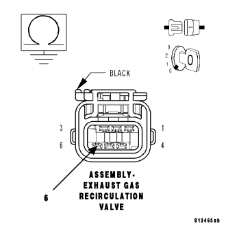
Is the resistance below 100 ohms?
Yes
- Repair the short to ground in the (K35) EGR Solenoid Control circuit.
- Perform the POWERTRAIN VERIFICATION TEST. (Refer to 9 - ENGINE - STANDARD PROCEDURE)
No
- Go To 9
9.(K35) EGR SOLENOID CONTROL CIRCUIT OPEN
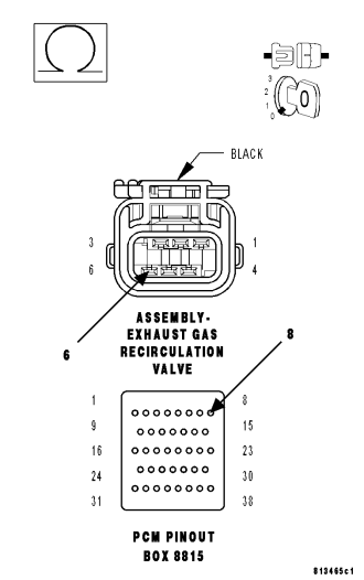
CAUTION: Do not probe the PCM harness connectors. Probing the PCM harness connectors will damage the PCM terminals resulting in poor terminal to pin connection. Install Miller Special Tool #8815 to perform diagnosis.
Is the resistance below 5.0 ohms?
Yes
- Go To 10
No
- Repair the open in the (K35) EGR Solenoid Control circuit.
- Perform the POWERTRAIN VERIFICATION TEST. (Refer to 9 - ENGINE - STANDARD PROCEDURE)
10.PCM
NOTE: Before continuing, check the PCM harness connector terminals for corrosion, damage, or terminal push out. Repair as necessary.
Were there any problems found?
Yes
- Repair as necessary.
- Perform the POWERTRAIN VERIFICATION TEST. (Refer to 9 - ENGINE - STANDARD PROCEDURE)
No
- Replace and program the Powertrain Control Module per Service Information.
- Perform the POWERTRAIN VERIFICATION TEST. (Refer to 9 - ENGINE - STANDARD PROCEDURE)