ASSEMBLY
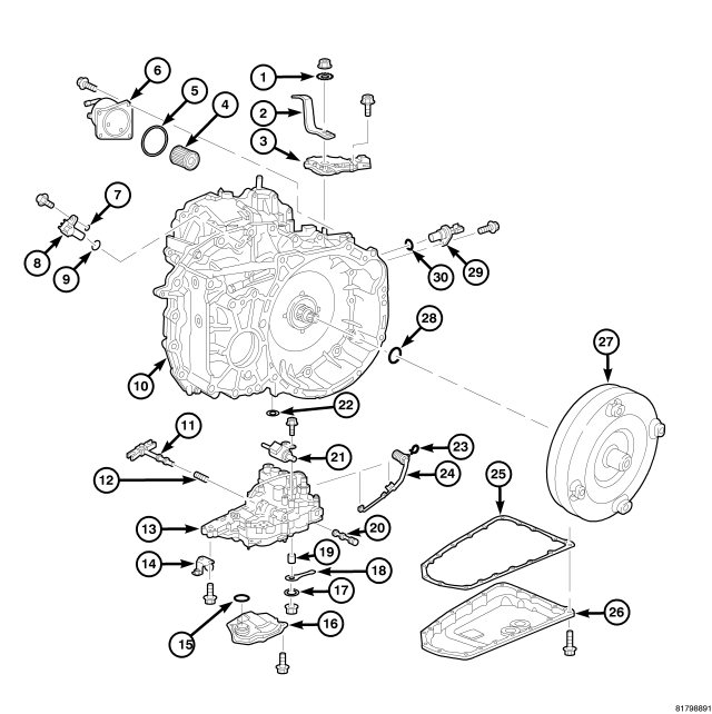
| 1- WASHER | 16 - OIL STRAINER |
| 2 - SHIFT LEVER | 17 - PLAIN WASHER |
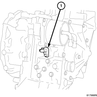
| 3 - INHIBITOR SWITCH | 18 - MANUAL LEVER |
| 4 - CVT FLUID FILTER | 19 - BUSHING |
| 5 - O-RING | 20 - MANUAL VALVE |
| 6 - CVT FLUID COOLER | 21 - STEPPER MOTOR |
| 7 - SHIM | 22 - LIP SEAL |
| 8 - OUTPUT SPEED SENSOR | 23 - SNAP RING |
| 9 - O-RING | 24 - VALVE BODY HARNESS |
| 10 - TRANSAXLE | 25 - OIL PAN GASKET |
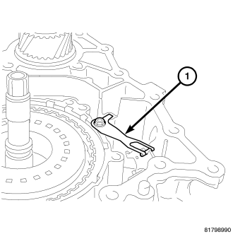
| 11 - PULLEY RATIO LINKAGE | 26 - OIL PAN |
| 12 - SPRING | 27 - TORQUE CONVERTER |
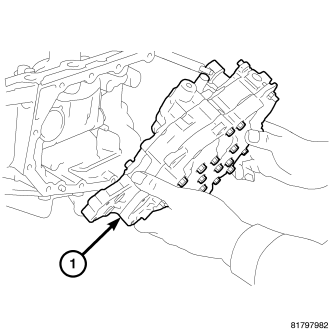
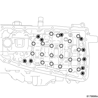
| 13 - CONTROL VALVE | 28 - O-RING |
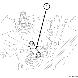
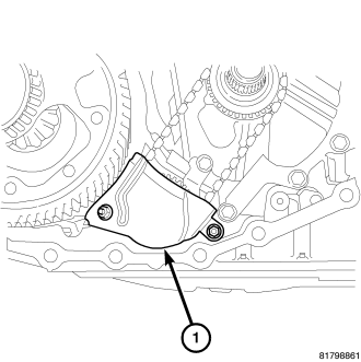
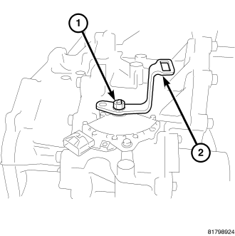
| 14 - BRACKET | 29 - INPUT SPEED SENSOR |
| 15 - O-RING | 30 - O-RING |
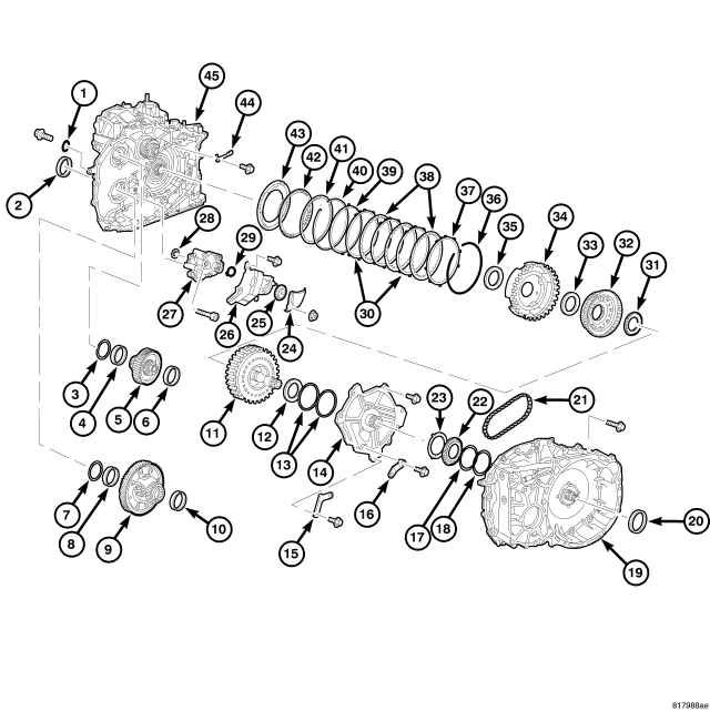
| 1 - O-RING | 24 - BAFFLE PLATE |
| 2 - SIDE OIL SEAL | 25 - DRIVEN SPROCKET (OIL PUMP) |
| 3 - ADJUSTABLE SHIM | 26 - BAFFLE PLATE |
| 4 - OUTER RACE | 27 - OIL PUMP |
| 5 - REDUCTION GEAR ASSEMBLY | 28 - LIP SEAL |
| 6 - OUTER RACE | 29 - SNAP RING |
| 7 - ADJUSTABLE SHIM | 30 - DRIVEN PLATES |
| 8 - OUTER RACE | 31 - NEEDLE BEARING |
| 9 - DIFFERENTIAL ASSEMBLY | 32 - SUN GEAR |
| 10 - OUTER RACE | 33 - NEEDLE BEARING |
| 11 - FORWARD CLUTCH ASSEMBLY | 34 - PLANETARY CARRIER |
| 12 - NEEDLE BEARING | 35 - NEEDLE BEARING |
| 13 - SEAL RING | 36 - SNAP RING |
| 14 - OIL PUMP COVER | 37 - RETAINING PLATE |
| 15 - BAFFLE PLATE | 38 - DRIVEN PLATES |
| 16 - BRACKET | 39 - DISH PLATE |
| 17 - ADJUSTABLE SHIM | 40 - SNAP RING |
| 18 - ADJUSTABLE SHIM | 41 - RETAINING PLATE |
| 19 - CONVERTER HOUSING | 42 - SPRING RETAINER ASSEMBLY |
| 20 - CONVERTER HOUSING OIL SEAL | 43 - REVERSE PLATE PISTON |
| 21 - OIL PUMP CHAIN | 44 - DETENT SPRING |
| 22 - DRIVE SPROCKET | 45 - TRANSAXLE CASE |
| 23 - THRUST WASHER |
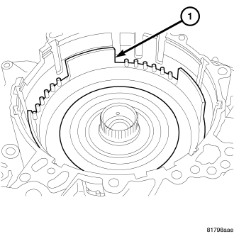
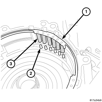
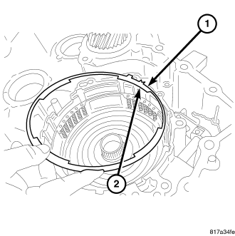
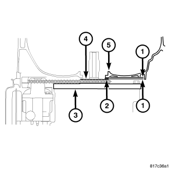
NOTE: The drive belt is directional and will need to be installed in the same direction as noted in disassembly. if installed incorrectly failure will occur.
CAUTION: Do not over tighten the compressor tool. Tighten to no more than 7 N·m (50 in. lbs.).
CAUTION: Remove moisture, oil, and used sealant from the sealant application surface. Make sure that the starting point and the ending point are between two bolt holes.
CAUTION: Inspect the reverse brake piston and, if damaged, replace it before installation. Apply CVT fluid to the seal when installing the reverse brake piston.
NOTE: Rotate reverse brake piston into place
NOTE: There is a notch in the retaining plate that points to the top of the case.
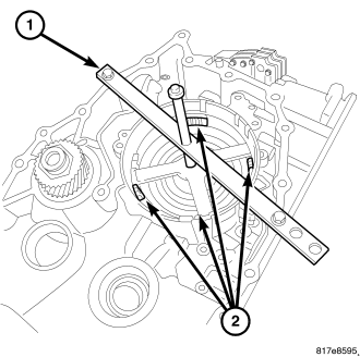
CAUTION: Set the spring compressor on top of the spring retainer assembly.
CAUTION: When conducting measurements, measure two or more places and calculate the average value.
CAUTION: Apply Vaseline or assembly lube when installing the needle bearing. Be careful to verify correct orientation of the needle bearing when installing it.
NOTE: The inner race will need to face down.
NOTE: The inner race will need to face down
CAUTION: Apply Vaseline or assembly lube when installing the needle bearing. Be careful to verify correct orientation of the needle bearing when installing it.
CAUTION: Apply Vaseline or assembly lube when installing the needle bearing. Be careful to verify correct orientation of the needle bearing when installing it.
NOTE: The inner race will need to face up.
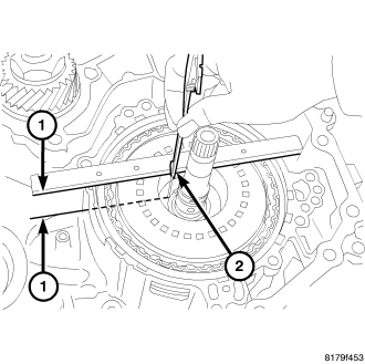
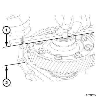
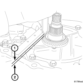
NOTE: Gauge bar 6311 can be used for doing the following measurement.
NOTE: Gauge bar 6311 can be used for doing the following measurement.
CAUTION: Apply Vaseline or assembly lube when installing the needle bearing. Be careful to verify correct orientation of the needle bearing when installing it.
| 1 - PRELOAD SHIM |
| 2 - DIFFERENTIAL ASSEMBLY |
| 3 - TRANSAXLE CASE |
| 4 - CONVERTER HOUSING |
CAUTION: When adjusting the preload, apply CVT fluid on the bearing to make it roll smoothly. When conducting measurements, measure two or more places and calculate the average value.
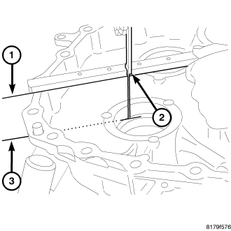
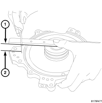
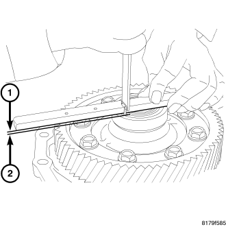
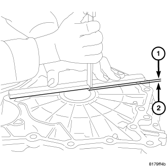
NOTE: Gauge bar 6311 can be used for doing the following measurement.
NOTE: Gauge bar 6311 can be used for doing the following measurement.
NOTE: Gauge bar 6311 can be used for doing the following measurement.
CAUTION: Do not re-use the select shim.
| 1 - REDUCTION GEAR |
| 2 - TRANSAXLE CASE |
| 3 - PRELOAD SHIM |
| 4 - BEARING OUTER RACE |

NOTE: Gauge bar 6311 can be used for doing the following measurement.
NOTE: Gauge bar 6311 can be used for doing the following measurement.
CAUTION: When adjusting the preload, apply CVT fluid on the bearing to make it roll smoothly. When conducting measurements, measure two or more places and calculate the average value.
NOTE: Gauge bar 6311 can be used for doing the following measurement.
CAUTION: Do not re-use the select shim.
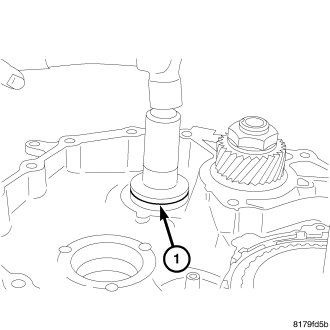
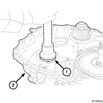
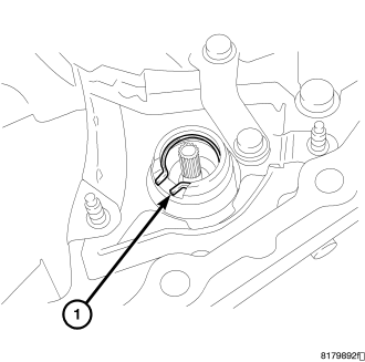
CAUTION: Do not re-use the lip seal. Apply CVT fluid when installing the lip seal.
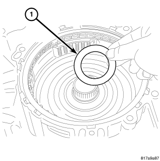
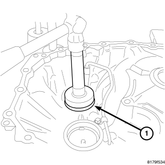
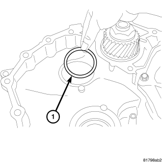
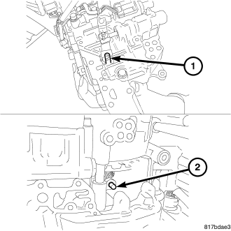
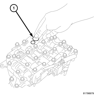
CAUTION: Do not re-use the o-ring. Apply CVT fluid when installing the O-ring.
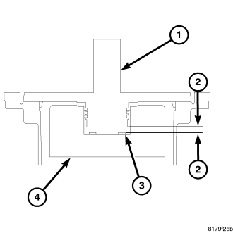
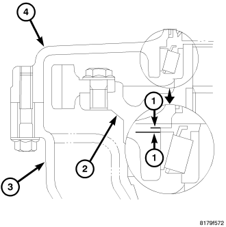
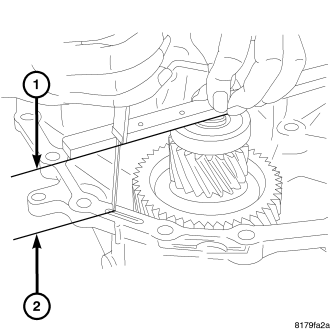
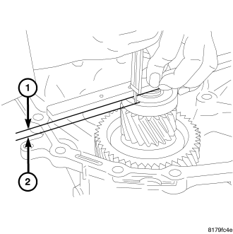
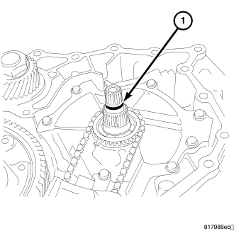
NOTE: One of the oil pump retaining bolts is installed from the outside of the transaxle case in the rear part of the oil pump.
CAUTION: Do not re-use the lip seal. Apply CVT fluid when installing the lip seal.
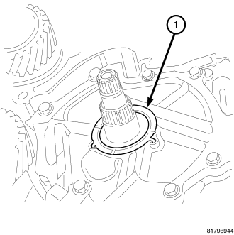
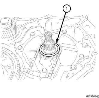
CAUTION: Apply CVT fluid when installing the bushing.
CAUTION: Do not re-use the o-ring. Apply CVT fluid when installing the o-ring.
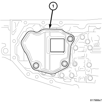
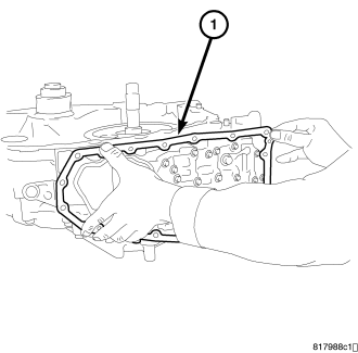
CAUTION: Do not re-use the oil pan gasket. Remove any moisture, oil, and used gasket material from the surface where the new gasket is to be installed. When installing the oil pan gasket, align the dowel pin with the dowel pin hole in the oil pan gasket.
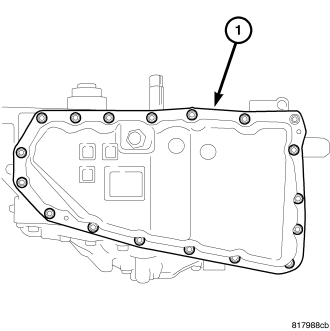
CAUTION: When installing the oil pan, align the dowel pin of the transaxle case with the dowel pin hole of the oil pan.
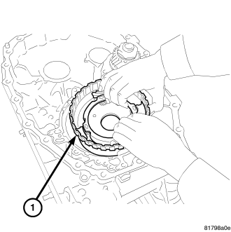
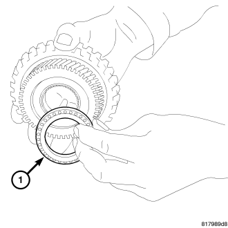
CAUTION: Do not re-use the seal rings. Apply Vaseline or assembly lube when installing the seal rings.
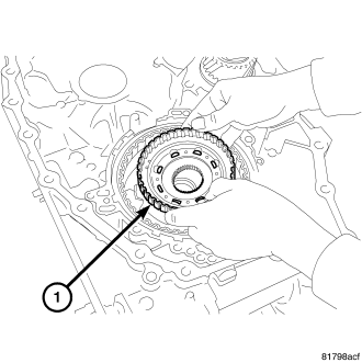
CAUTION: Be sure to align the pawl of the thrust washer with the alignment hole of the oil pump cover. Apply Vaseline or assembly lube when installing the thrust washer.
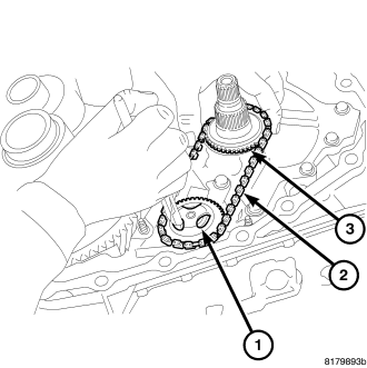
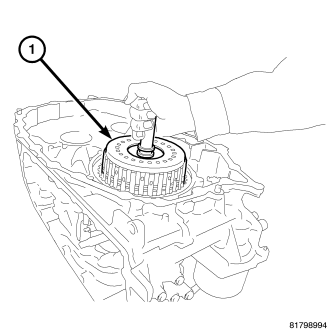
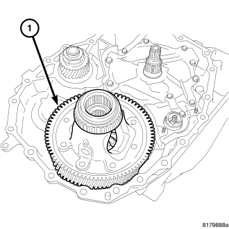
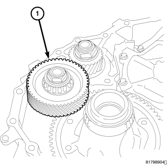
CAUTION: When necessary to replace any of the driven sprocket, oil pump chain, or drive sprocket, replace all components as a matched set. Pull the driven sprocket up softly and check that the driven sprocket is securely installed.
NOTE: Gauge bar 6311 can be used for doing the following measurement.
NOTE: Gauge bar 6311 can be used for doing the following measurement.
CAUTION: Do not re-use the o-ring. Apply CVT fluid when installing the o-ring.
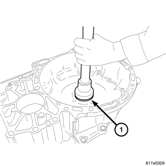
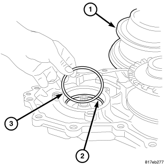
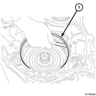
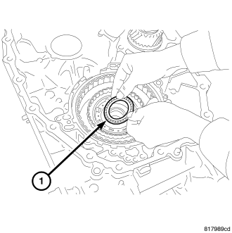
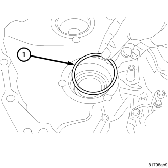
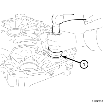
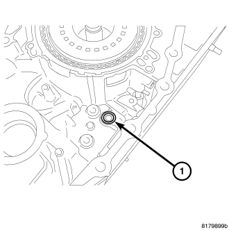
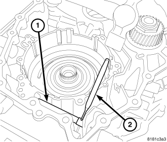
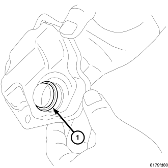
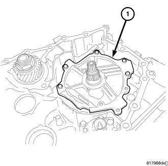
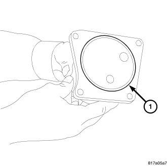
CAUTION: Do not re-use the converter housing oil seal (1). Apply CVT fluid when installing the converter housing oil seal (1).
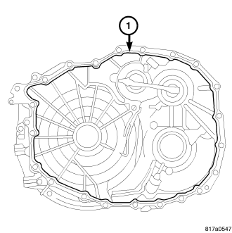
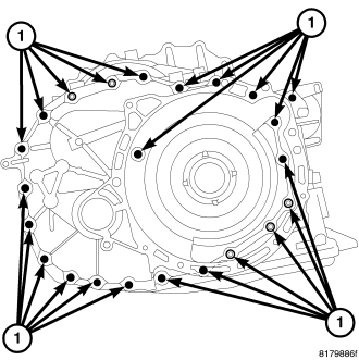
CAUTION: Remove moisture, oil, and used sealant from the sealant application surface. Make sure that the starting point and the ending point are between two bolt holes.
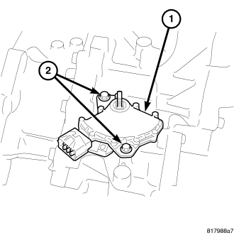
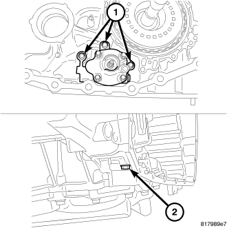
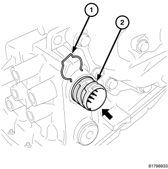
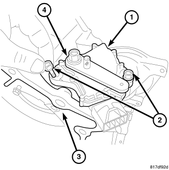
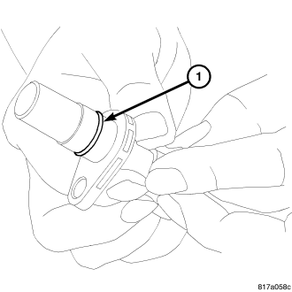
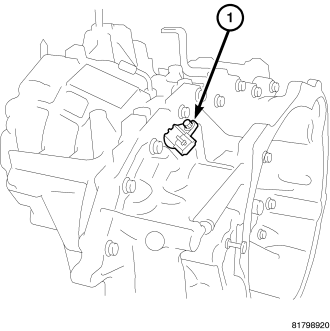
CAUTION: Do not re-use the TRS transmission range sensor.
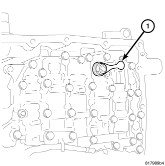
CAUTION: Do not re-use the o-ring. Apply CVT fluid when installing the o-ring.
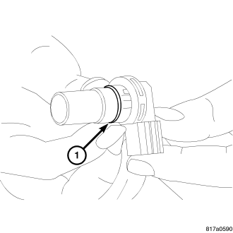
CAUTION: Do not re-use the o-ring. Apply CVT fluid when installing the o-ring.
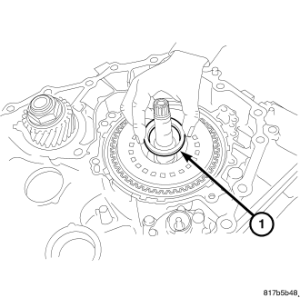
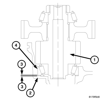
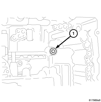
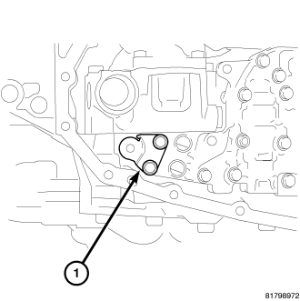
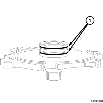
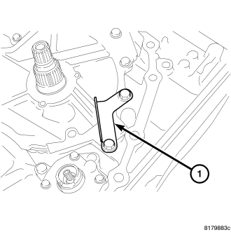
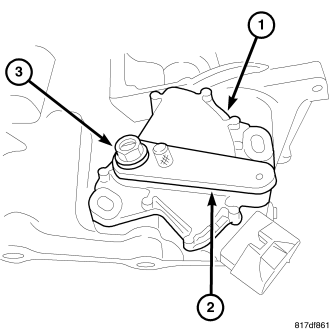
CAUTION: Be sure to install the select shim between the secondary speed sensor and the converter housing before installing the secondary speed sensor.
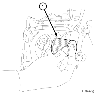
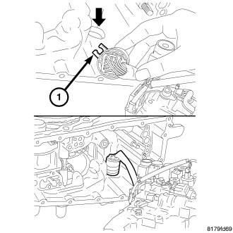
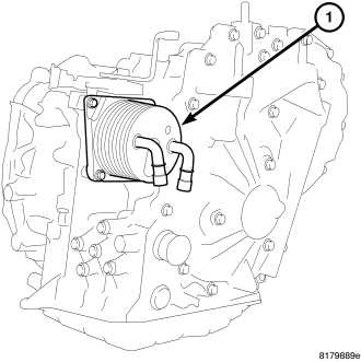
CAUTION: Apply CVT fluid on the seal part when installing the CVT fluid filter.
CAUTION: Do not re-use the o-ring. Apply CVT fluid when installing the o-ring.
NOTE: Gauge bar 6311 can be used for doing the following measurement.
NOTE: When conducting measurements, measure two or more places and calculate the average value.
NOTE: Use the designated brand of CVT fluid. Use of other brands of CVT fluid other than the designated brand will deteriorate the driveability and the durability of the CVT, and will cause damage to the CVT.
(Refer to 21 - TRANSMISSION/TRANSAXLE/AUTOMATIC - CVT/FLUID - STANDARD PROCEDURE)